ANALOG DEVICES OP183 User Guide
Summary
The OP183 is a high-performance, single-supply operational amplifier featuring a 5 MHz bandwidth and 10 V/μs slew rate. It operates reliably across an extensive voltage range, from 3V up to 36V, making it ideal for demanding audio and signal processing applications. This manual provides comprehensive technical specifications, application circuits, and performance data necessary for incorporating the amplifier into telecom, multimedia, and instrumentation designs. It is tailored for engineers requiring stable, low-noise amplification in single-supply configurations.
Page 1 Text Content
5 MHz Single-Supply Operational Amplifier
OP183
FEATURES PIN CONNECTION Single supply: 3 V to 36 V
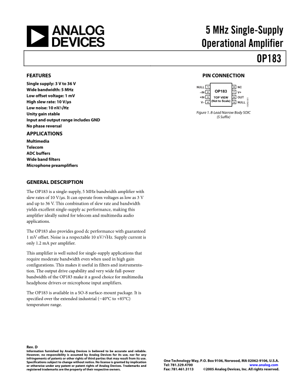
NULL NC
Wide bandwidth: 5 MHz
–IN OP183 V+
Low offset voltage: 1 m V
+IN TOP VIEW OUT
(Not to Scale)
High slew rate: 10 V/μs V– NULL Low noise: 10 n V/√Hz
Figure 1. 8-Lead Narrow Body SOIC
Unity gain stable
(S Suffix)
Input and output range includes GND No phase reversal APPLICATIONS Multimedia Telecom ADC buffers Wide band filters Microphone preamplifiers
GENERAL DESCRIPTION The OP183 is a single-supply, 5 MHz bandwidth amplifier with slew rates of 10 V/μs. It can operate from voltages as low as 3 V and up to 36 V. This combination of slew rate and bandwidth yields excellent single-supply ac performance, making this amplifier ideally suited for telecom and multimedia audio applications.
The OP183 also provides good dc performance with guaranteed 1 m V offset. Noise is a respectable 10 n V/√Hz. Supply current is only 1.2 m A per amplifier.
This amplifier is well suited for single-supply applications that require moderate bandwidth even when used in high gain configurations. This makes it useful in filters and instrumenta- tion. The output drive capability and very wide full-power bandwidth of the OP183 make it a good choice for multimedia headphone drivers or microphone input amplifiers.
The OP183 is available in a SO-8 surface-mount package. It is specified over the extended industrial (−40°C to +85°C) temperature range.
Rev. D Information furnished by Analog Devices is believed to be accurate and reliable. However, no responsibility is assumed by Analog Devices for its use, nor for any infringements of patents or other rights of third parties that may result from its use.
One Technology Way, P.O. Box 9106, Norwood, MA 02062-9106, U.S.A.
Specifications subject to change without notice. No license is granted by implication
or otherwise under any patent or patent rights of Analog Devices. Trademarks and Tel: 781.329.4700 www.analog.com registered trademarks are the property of their respective owners. Fax: 781.461.3113 ©2005 Analog Devices, Inc. All rights reserved.
Page Summary Contents For ANALOG DEVICES OP183 User Guide
Manual Details
| Brand | Analog Devices |
|---|---|
| Pages | 16 |
| File Size | 341.93 KB |
| Published | June 15, 2026 |
Enter the captcha to get the download link:

Frequently Asked Questions
What is the operating voltage range for the OP183 amplifier?
It can operate from voltages as low as 3 V up to 36 V, making it single-supply compatible.
How wide is the operational bandwidth and what are its slew rate specifications?
The amplifier offers a wide bandwidth of 5 MHz and has a high slew rate of 10 V/μs.
Is this amplifier suitable for challenging environmental conditions like varying temperatures?
Yes, it is specified over the extended industrial temperature range of -40°C to +85°C.
What is the typical quiescent current draw for using the OP183?
The supply current is only 1.2 mA per amplifier.