ANALOG DEVICES AD7874 Data Sheet
Summary
The AD7874 is a professional 4-channel, 12-bit simultaneous sampling data acquisition system designed for precise signal measurement. Ideal for complex applications like phased-array sonar and motor control systems, it captures the relative phase of four input channels simultaneously. This manual details its high-speed features, including up to a 29 kHz sample rate per channel, guaranteed low aperture delay matching, and direct integration with modern microprocessors. Use this powerful tool when maintaining signal integrity across multiple inputs is critical.
Page 1 Text Content
LC2MOS 4-Channel, 12-Bit Simultaneous Sampling Data Acquisition System
AD7874
FEATURES
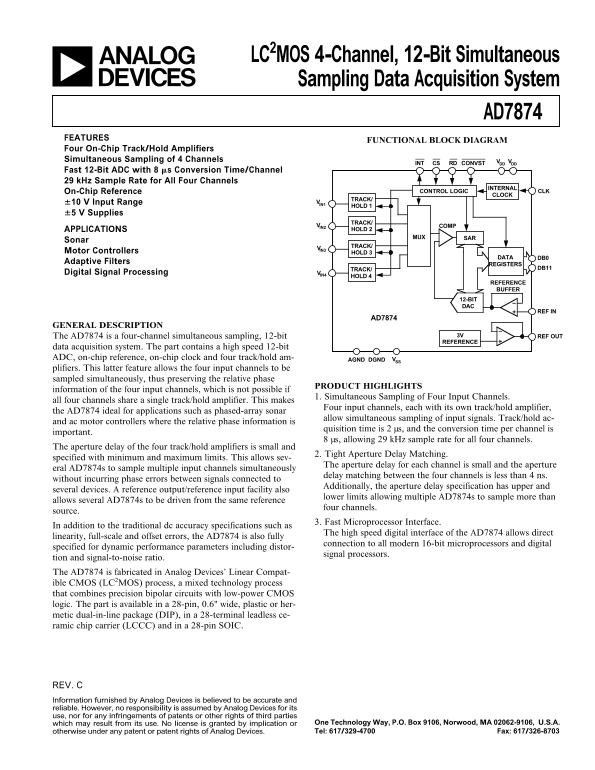
FUNCTIONAL BLOCK DIAGRAM
Four On-Chip Track/Hold Amplifiers Simultaneous Sampling of 4 Channels VDD VDD
INT CS RD CONVST
Fast 12-Bit ADC with 8 ms Conversion Time/Channel 29 k Hz Sample Rate for All Four Channels
INTERNAL
On-Chip Reference CONTROL LOGIC CLK
CLOCK
TRACK/
610 V Input Range VIN1
HOLD 1
65 V Supplies
TRACK/
VIN2 COMP
APPLICATIONS HOLD 2
SAR MUX
Sonar
TRACK/
Motor Controllers HOLD 3
DATA DB0
Adaptive Filters
REGISTERS
TRACK/ DB11
Digital Signal Processing VIN4
HOLD 4
REFERENCE BUFFER
12-BIT DAC
REF IN
AD7874
GENERAL DESCRIPTION
The AD7874 is a four-channel simultaneous sampling, 12-bit REF OUT3V
REFERENCE
data acquisition system. The part contains a high speed 12-bit ADC, on-chip reference, on-chip clock and four track/hold am- AGND DGND VSS plifiers. This latter feature allows the four input channels to be sampled simultaneously, thus preserving the relative phase
PRODUCT HIGHLIGHTS
information of the four input channels, which is not possible if
1. Simultaneous Sampling of Four Input Channels.
all four channels share a single track/hold amplifier. This makes
Four input channels, each with its own track/hold amplifier,
the AD7874 ideal for applications such as phased-array sonar
allow simultaneous sampling of input signals. Track/hold ac-
and ac motor controllers where the relative phase information is
quisition time is 2 µs, and the conversion time per channel is
important.
8 µs, allowing 29 k Hz sample rate for all four channels.
The aperture delay of the four track/hold amplifiers is small and
2. Tight Aperture Delay Matching.
specified with minimum and maximum limits. This allows sev-
The aperture delay for each channel is small and the aperture
eral AD7874s to sample multiple input channels simultaneously
delay matching between the four channels is less than 4 ns.
without incurring phase errors between signals connected to
Additionally, the aperture delay specification has upper and
several devices. A reference output/reference input facility also
lower limits allowing multiple AD7874s to sample more than
allows several AD7874s to be driven from the same reference
four channels.
source.
3. Fast Microprocessor Interface.
In addition to the traditional dc accuracy specifications such as
The high speed digital interface of the AD7874 allows direct
linearity, full-scale and offset errors, the AD7874 is also fully
connection to all modern 16-bit microprocessors and digital
specified for dynamic performance parameters including distor-
signal processors.
tion and signal-to-noise ratio. The AD7874 is fabricated in Analog Devices’ Linear Compat- ible CMOS (LC2MOS) process, a mixed technology process that combines precision bipolar circuits with low-power CMOS logic. The part is available in a 28-pin, 0.6" wide, plastic or her- metic dual-in-line package (DIP), in a 28-terminal leadless ce- ramic chip carrier (LCCC) and in a 28-pin SOIC.
REV. Information furnished by Analog Devices is believed to be accurate and reliable. However, no responsibility is assumed by Analog Devices for its use, nor for any infringements of patents or other rights of third parties
which may result from its use. No license is granted by implication or One Technology Way, P.O. Box 9106, Norwood, MA 02062-9106, U.S.A. otherwise under any patent or patent rights of Analog Devices. Tel: 617/329-4700 Fax: 617/326-8703
Page Summary Contents For ANALOG DEVICES AD7874 Data Sheet
Manual Details
| Brand | Analog Devices |
|---|---|
| Pages | 16 |
| File Size | 414.44 KB |
| Published | June 16, 2026 |
Enter the captcha to get the download link:
