ADMA711/2 DATA MANUAL -Specifications, Instructions, and Definitions for the ADM811/2 Analog Devices
Summary
The ADM811/ADM812 series are reliable voltage monitoring ICs designed to protect sophisticated electronic systems from unstable power. These devices constantly monitor multiple core voltages, triggering a system reset when supplied power drops below specified safety thresholds. This manual details comprehensive specifications, functional block diagrams, and circuit schematics, providing users with the technical depth needed for integration. Ideal for developers of microprocessor systems, controllers, automotive equipment, and critical safety instruments requiring maximum operational reliability.
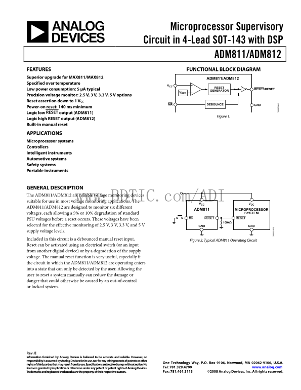
Page 1 Text Content
Microprocessor Supervisory Circuit in 4-Lead SOT-143 with DSP
ADM811/ADM812 FEATURES FUNCTIONAL BLOCK DIAGRAM Superior upgrade for MAX811/MAX812
ADM811/ADM812
Specified over temperature
RESET
Low power consumption: 5 μA typical RESET/RESET
GENERATOR
Precision voltage monitor: 2.5 V, 3 V, 3.3 V, 5 V options Reset assertion down to 1 VCC
MR DEBOUNCE GND
Power-on reset: 140 ms minimum Logic low RESET output (ADM811)
Figure 1.
Logic high RESET output (ADM812) Built-in manual reset
APPLICATIONS Microprocessor systems Controllers Intelligent instruments Automotive systems Safety systems Portable instruments
GENERAL DESCRIPTION The ADM811/ADM812 are reliable voltage monitoring devices
suitable for use in most voltage monitoring applications. The www.BDTIC.com/ADI
VCC VCC
ADM811/ADM812 are designed to monitor six different
ADM811 MICROPROCESSOR
voltages, each allowing a 5% or 10% degradation of standard SYSTEM
MR RESET RESET
PSU voltages before a reset occurs. These voltages have been
selected for the effective monitoring of 2.5 V, 3 V, 3.3 V, and 5 V GND GND supply voltage levels.
Included in this circuit is a debounced manual reset input.
Figure 2. Typical ADM811 Operating Circuit
Reset can be activated using an electrical switch (or an input from another digital device) or by a degradation of the supply voltage. The manual reset function is very useful, especially if the circuit in which the ADM811/ADM812 are operating enters into a state that can only be detected by the user. Allowing the
user to reset a system manually can reduce the damage or
danger that could otherwise be caused by an out-of-control or locked system.
Rev. E Information furnished by Analog Devices is believed to be accurate and reliable. However, no responsibility is assumed by Analog Devices for its use, nor for any infringements of patents or other
One Technology Way, P.O. Box 9106, Norwood, MA 02062-9106, U.S.A.
rights of third parties that may result from its use. Specifications subject to change without notice. No
license is granted by implication or otherwise under any patent or patent rights of Analog Devices. Tel: 781.329.4700 www.analog.com Trademarks and registered trademarks are the property of their respective owners. Fax: 781.461.3113 ©2008 Analog Devices, Inc. All rights reserved.
Page Summary Contents For ADMA711/2 DATA MANUAL -Specifications, Instructions, and Definitions for the ADM811/2 Analog Devices
Manual Details
| Brand | Analog Devices |
|---|---|
| Pages | 12 |
| File Size | 278.03 KB |
| Published | May 14, 2026 |
Enter the captcha to get the download link:

Frequently Asked Questions
What systems are suitable for ADM811/ADM812 use?
They are suitable for microprocessor systems, controllers, intelligent instruments, automotive, and safety systems.
How is a manual reset activated in the circuit?
The unit includes a debounced manual reset input, allowing user detection of system states.
What does the ADM811/ADM812 monitor voltages for?
They are designed to monitor six different processor voltages (VCC, V_CC, etc.) and include options at 2.5V, 3V, 3.3V, and 5V.
What is the functionality of the reset mechanism?
The unit detects a supply voltage degradation (5% or 10%) before triggering a reset output.