AD7827 Analog Devices Data Handbook/Manual
Summary
The AD7827 is a high-speed, low-power 8-bit Analog-to-Digital Converter (ADC) designed for sophisticated real-time data acquisition systems. Operating efficiently from a single 3V or 5V supply, this module features a fast 420 ns conversion time and includes an on-chip track-and-hold amplifier. The manual provides comprehensive details on its seamless integration with Digital Signal Processors (DSPs) via a dedicated serial interface. Essential for engineers building DSP applications requiring precise sampling control, the AD7827 ensures reliable performance in compact hardware designs.
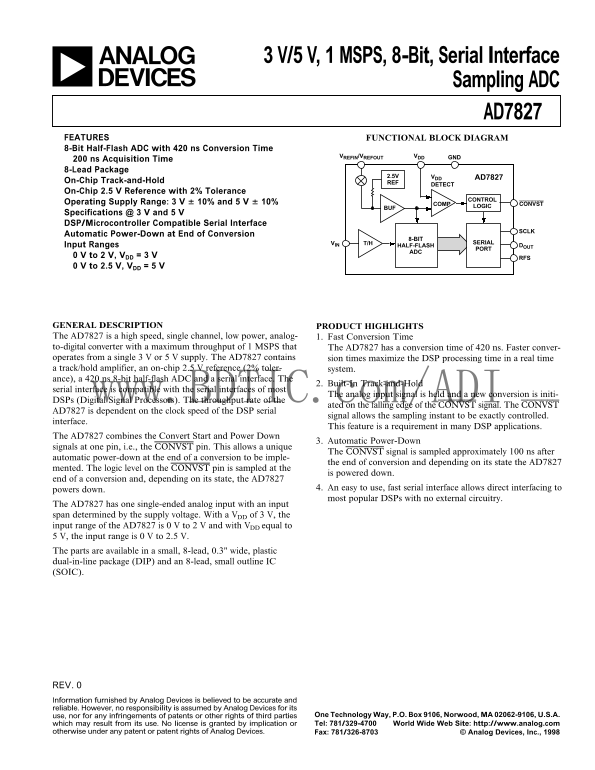
Page 1 Text Content
3 V/5 V, 1 MSPS, 8-Bit, Serial Interface
Sampling ADC AD7827 FUNCTIONAL BLOCK DIAGRAMFEATURES
8-Bit Half-Flash ADC with 420 ns Conversion Time
GNDVDDVREFIN/VREFOUT
200 ns Acquisition Time 8-Lead Package
2.5V VDD AD7827
On-Chip Track-and-Hold REF
DETECT
On-Chip 2.5 V Reference with 2% Tolerance
CONTROL
Operating Supply Range: 3 V 6 10% and 5 V 6 10% COMP CONVST
BUF LOGIC
Specifications @ 3 V and 5 V DSP/Microcontroller Compatible Serial Interface
Automatic Power-Down at End of Conversion
8-BIT
VIN T/H SERIAL
Input Ranges HALF-FLASH DOUT
0 V to 2 V, VDD = 3 V
0 V to 2.5 V, VDD = 5 V
GENERAL DESCRIPTION PRODUCT HIGHLIGHTS The AD7827 is a high speed, single channel, low power, analog- 1. Fast Conversion Time to-digital converter with a maximum throughput of 1 MSPS that The AD7827 has a conversion time of 420 ns. Faster conver- operates from a single 3 V or 5 V supply. The AD7827 contains sion times maximize the DSP processing time in a real time a track/hold amplifier, an on-chip 2.5 V reference (2% toler- system. ance), a 420 ns 8-bit half-flash ADC and a serial interface. The
2. Built-In Track-and-Hold
serial interface is compatible with the serial interfaces of most
The analog input signal is held and a new conversion is initi-
DSPs (Digital Signal Processors). The throughput rate of the www.BDTIC.c m/ADI
ated on the falling edge of the CONVST signal. The CONVST
AD7827 is dependent on the clock speed of the DSP serial
signal allows the sampling instant to be exactly controlled.
interface.
This feature is a requirement in many DSP applications.
The AD7827 combines the Convert Start and Power Down
3. Automatic Power-Down
signals at one pin, i.e., the CONVST pin. This allows a unique
The CONVST signal is sampled approximately 100 ns after
automatic power-down at the end of a conversion to be imple-
the end of conversion and depending on its state the AD7827
mented. The logic level on the CONVST pin is sampled at the
is powered down.
end of a conversion and, depending on its state, the AD7827
4. An easy to use, fast serial interface allows direct interfacing to
powers down.
most popular DSPs with no external circuitry.
The AD7827 has one single-ended analog input with an input span determined by the supply voltage. With a VDD of 3 V, the input range of the AD7827 is 0 V to 2 V and with VDD equal to 5 V, the input range is 0 V to 2.5 V. The parts are available in a small, 8-lead, 0.3" wide, plastic dual-in-line package (DIP) and an 8-lead, small outline IC (SOIC).
REV. Information furnished by Analog Devices is believed to be accurate and reliable. However, no responsibility is assumed by Analog Devices for its
use, nor for any infringements of patents or other rights of third parties One Technology Way, P.O. Box 9106, Norwood, MA 02062-9106, U.S.A. which may result from its use. No license is granted by implication or Tel: 781/329-4700 World Wide Web Site: http://www.analog.com
otherwise under any patent or patent rights of Analog Devices. Fax: 781/326-8703 © Analog Devices, Inc., 1998
Page Summary Contents For AD7827 Analog Devices Data Handbook/Manual
Manual Details
| Brand | Analog Devices |
|---|---|
| Pages | 12 |
| File Size | 124.80 KB |
| Published | June 15, 2026 |
Enter the captcha to get the download link:
