# A B C D E F G H I J K L M N O P Q R S T U V W X Y Z

AD5282 Analog Devices Data Handbook/Manual

Summary

These digitally controlled potentiometers are essential components for precise analog signal adjustment in complex electronic systems. Featuring single or dual channels, 256 programmable positions, and an SPI interface, they provide robust resistance control for applications like LED drivers, gain/offset instrumentation, and multimedia circuits. This guide provides comprehensive details on operation, electrical specifications, programming sequences, and integration strategies, making it a vital resource for electronics designers building high-precision communication or audio equipment.
📄 Preview 📖 Table of Contents Contents PAGE OF 28

Page 1 Text Content

Single/Dual, +15 V/±5 V, 256-Position, I2C-Compatible Digital Potentiometer

AD5280/AD5282

FEATURES logic outputs that enable users to drive digital loads, logic gates, LED drivers, and analog switches in their system.

AD5280: 1 channel

AD5282: 2 channels The AD5280/AD5282 are available in thin, surface-mounted 256 positions 14-lead TSSOP and 16-lead TSSOP. All parts are guaranteed to

5 V to 15 V single supply; ±5.5 V dual-supply operation operate over the extended industrial temperature range of Fixed terminal resistance: 20 kΩ, 50 kΩ, 200 kΩ −40°C to +85°C. For 3-wire SPI-compatible interface applica- Low temperature coefficient: 30 ppm/°C tions, see the AD5260/AD5262 product information on Power-on midscale preset1 www.analog.com. Programmable reset

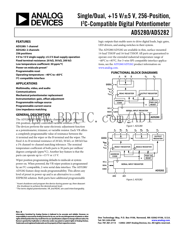
FUNCTIONAL BLOCK DIAGRAMS

Operating temperature: −40o C to +85o C

I2C-compatible interface

APPLICATIONS

Multimedia, video, and audio VDD

Communications VL

VSS RDAC REGISTER OUTPUT REGISTER

Mechanical potentiometer replacement Instrumentation: gain, offset adjustment

ADDRESS

Programmable voltage source CODE PWR ON RESET

Programmable current source

Line impedance matching

SERIAL INPUT REGISTER

GENERAL DESCRIPTION GND

AD5280

The AD5280/AD5282 are single-channel and dual-channel,

www.BDTIC.com/ADI AD0 AD1 256-position, digitally controlled variable resistors (VRs)2.

Figure 1. AD5280

The devices perform the same electronic adjustment function

as a potentiometer, trimmer, or variable resistor. Each VR offers A1 W1 B1 A2 W2 B2 O1

a completely programmable value of resistance between the

OUTPUT

A terminal and the wiper or the B terminal and the wiper. The

SHDN REGISTER

fixed A-to-B terminal resistance of 20 kΩ, 50 kΩ, or 200 kΩ has

a 1% channel-to-channel matching tolerance. The nominal VL

RDAC1 REGISTER RDAC2 REGISTER

temperature coefficient of both parts is 30 parts per million/ degrees centigrade (ppm/°C). Another key feature is that the

ADDRESS

parts can operate up to +15 V or ±5 V. PWR ON

RESET

Wiper position programming defaults to midscale at system

SCL 9-

power-on. When powered, the VR wiper position is programmed SERIAL INPUT REGISTER

by an I2C-compatible, 2-wire serial data interface. The AD5280/

AD5282 feature sleep mode programmability. This allows any AD5282

level of preset in power-up and is an alternative to a costly

AD0 AD1

EEPROM solution. Both parts have additional programmable

Figure 2. AD5282

1 Assert shutdown and program the device during power-up, then deassert

the shutdown to achieve the desired preset level. 2 The terms digital potentiometer, VR, and RDAC are used interchangeably.

Rev. B Information furnished by Analog Devices is believed to be accurate and reliable. However, no responsibility is assumed by Analog Devices for its use, nor for any infringements of patents or other

One Technology Way, P.O. Box 9106, Norwood, MA 02062-9106, U.S.A.

rights of third parties that may result from its use. Specifications subject to change without notice. No

license is granted by implication or otherwise under any patent or patent rights of Analog Devices. Tel: 781.329.4700 www.analog.com Trademarks and registered trademarks are the property of their respective owners. Fax: 781.461.3113 ©2002–2007 Analog Devices, Inc. All rights reserved.

Page Summary Contents For AD5282 Analog Devices Data Handbook/Manual

Page 1 Single/Dual, +15 V/±5 V, 256-Position, I2C-Compatible Digital Potentiometer AD5280/AD5282 FEATURES logic outputs that enable users to drive digital loads, logic gates, LED drivers, and analog switches...
Page 2 AD5280/AD5282 TABLE OF CONTENTS Features Multiple Devices on One Bus Applications....................................................................................... Level Shift for Bidirectional I...
Page 3 AD5280/AD5282 SPECIFICATIONS ELECTRICAL CHARACTERISTICS VDD = +15 V, VSS = 0 V or VDD = +5 V, VSS = −5 V; VLOGIC = 5 V, VA = +VDD, VB = 0 V; −40°C < TA < +85°C, unless otherwise noted. Table 1. ...
Page 4 AD5280/AD5282 Parameter Symbol Conditions Min Typ1 Max Unit Total Harmonic Distortion THDW VA = 1 V rms, RAB = 20 kΩ 0.014 % VB = 0 V dc, f = 1 k Hz VW Settling Time t S VA = 5 V, VB = 5 V, ±1 LSB err...
Page 5 AD5280/AD5282 ABSOLUTE MAXIMUM RATINGS TA = 25°C, unless otherwise noted. Stresses above those listed under Absolute Maximum Ratings may cause permanent damage to the device. This is a stress Table 2....
Page 6 AD5280/AD5282 PIN CONFIGURATIONS AND FUNCTION DESCRIPTIONS VL A1 W2 AD5280 O2 W1 B2 TOP VIEW AD5282 VDD VSS B1 TOP VIEW VL SHDN GND VDD VSS SCL AD1 SHDN GND SDA AD0 SCL AD1 SDA AD0 Figure 4. AD5280 Pi...
Page 7 AD5280/AD5282 PO TE TI ET ER IN (L SB EO ST -D (L SB EO ST -IN (L SB TYPICAL PERFORMANCE CHARACTERISTICS 1.0 0.5 RAB = 20kΩ RAB = 20kΩ TA = 25°C 0.4 0.2 TA = –40°C TA = +85°C TA = +25°C CODE (Decimal)...
Page 8 FU LL -S LE (L SB -IN (L SB IN (L SB AD5280/AD5282 1.0 2.0 RAB = 20kΩ RAB = 20kΩ TA = 25°C AVG +3σ 0.5 VDD/VSS = +5V/0V AVG 1.4 AVG –3σ VDD/VSS = ±5V VDD/VSS = +15V/0V |VDD – VSS| (V) TEMPERATURE (°C)...
Page 9 AD5280/AD5282 PO TE TI ET ER TE PC (p pm /° EO ST AT TE PC (p pm /° IC (µ RAB = 20kΩ 80H TA = 25°C VDD/VSS = 5V/0V VLOGIC = 5V VDD/VSS = 5V/0V TA = 25°C VLOGIC = 3V –54 VA = 50m V rms VDD/VSS = ±5V 10...
Page 10 IC (m IN LI ZE IN LA TN ES (0 .1 d B /D IV IN (d AD5280/AD5282 R = 20kΩ CODE = 80H, VA = VDD, VB = 0V –6 310k Hz –PSRR @ VDD/VSS = ±5V R = 50kΩ DC ±10% p-p AC 150k Hz 35k Hz +PSRR @ VDD/VSS = ±5V DC ±...
Page 11 AD5280/AD5282 TH EO ET IC _M (m A2 1.0V 33.41µs CODES SET TO MIDSCALE 3 LOTS SAMPLE SIZE = 135 LONG TERM CHANNEL-TO-CHANNEL RAB MATCH (%) Figure 30. Digital Feedthrough vs. Time Figure 32. Channel-to-...
Page 12 AD5280/AD5282 TEST CIRCUITS Figure 33 to Figure 43 define the test conditions used in the product specification table. DUT V+ = VDD DUTA 1LSB = V+/2N VMS OP279 VOUTOFFSET OFFSET BIAS Figure 33. Potent...
Page 13 AD5280/AD5282 A1 VDD A2 NC = NO CONNECT RDAC1 RDAC2 VDD ICMA VIN N/C VOUT VSS GND VCM B1 VSS CTA = 20 LOG [VOUT/VIN] Figure 41. Common-Mode Leakage Current Figure 43. Analog Crosstalk (AD5282 Only) IL...
Page 14 AD5280/AD5282 THEORY OF OPERATION The AD5280/AD5282 are single-channel and dual-channel, The general equation determining the digitally programmed 256-position, digitally controlled variable resistors...
Page 15 AD5280/AD5282 Operation of the digital potentiometer in divider mode results input voltage applied to Terminal A and Terminal B is in a more accurate operation over temperature. Unlike rheostat VDVDDV...
Page 16 AD5280/AD5282 DIGITAL INTERFACE 2-WIRE SERIAL BUS The AD5280/AD5282 are controlled via an I2C-compatible serial operation does not disturb the contents of the register. When bus. The RDACs are connect...
Page 17 AD5280/AD5282 READBACK RDAC VALUE The AD5280/AD5282 allow the user to read back the RDAC In addition, shutdown can be implemented with the device values in read mode. However, for the dual-channel AD5...
Page 18 AD5280/AD5282 LEVEL SHIFT FOR BIDIRECTIONAL INTERFACE While most old systems can be operated at one voltage, a new component can be optimized at another. When two systems operate the same signal at tw...
Page 19 AD5280/AD5282 LAYOUT AND POWER SUPPLY BYPASSING VDD VDD C3 C1 It is a good practice to design a layout with compact, minimum 10µF 0.1µF AD5280/ lead lengths. The leads to the input should be as direct...
Page 20 AD5280/AD5282 APPLICATIONS INFORMATION Depending on the op amp GBP, reducing the feedback resistor BIPOLAR DC OR AC OPERATION FROM DUAL may extend the zero’s frequency far enough to overcome the SUPPL...
Page 21 AD5280/AD5282 8-BIT BIPOLAR DAC As in the previous example, in the simpler and more common case where K = 1, a single digital AD5280 potentiometer is V1 OP2177 used. U1 is replaced by a matched pair o...
Page 22 AD5280/AD5282 PROGRAMMABLE CURRENT SOURCE PROGRAMMABLE BIDIRECTIONAL CURRENT +5V SOURCE VIN TO (2.048 + VL) SLEEP VOUT REF191 10p F C1 GND 1µF RS V+ 102Ω OP2177 AD5280 V+ 50kΩ AD5280 –15V OP8510 V+ TO...
Page 23 AD5280/AD5282 PROGRAMMABLE LOW-PASS FILTER In analog-to-digital conversion applications, it is common to At resonance, setting the following balances the bridge: include an antialiasing filter to band...
Page 24 AD5280/AD5282 RDAC CIRCUIT SIMULATION MODEL MACRO MODEL NET LIST FOR RDAC The internal parasitic capacitances and the external capacitive .PARAM D=256, RDAC=20E3 loads dominate the ac characteristics ...
Page 25 AD5280/AD5282 OUTLINE DIMENSIONS 4.40 6.40 BSC PIN 1 1.05 0.65 BSC MAX 0.09 0.75 SEATING 0.45 0.19 COPLANARITY PLANE COMPLIANT TO JEDEC STANDARDS MO-153-AB-1 Figure 66. 14-Lead Thin Shrink Small Outli...
Page 26 AD5280/AD5282 ORDERING GUIDE No. of Temperature Package Model1 Channels RAB (kΩ) Range Package Description Option Ordering Quantity AD5280BRU20 1 20 −40°C to +85°C 14-Lead TSSOP RU-14 96 AD5280BRU20-R...
Page 27 AD5280/AD5282 NOTES www.BDTIC.com/ADI Rev. B | Page 27 of 28
Page 28 AD5280/AD5282 NOTES www.BDTIC.com/ADI ©2002–2007 Analog Devices, Inc. All rights reserved. Trademarks and registered trademarks are the property of their respective owners. C02929-0-8/07(B) Rev. B | P...

Manual Details

Brand Analog Devices
Pages 28
File Size 671.03 KB
Published May 14, 2026
126 views

Enter the captcha to get the download link:

captcha

Frequently Asked Questions

What operating temperature range do these potentiometers support?

They operate over an extended industrial temperature range of -40°C to +85°C.

How is the resistance value programmed or adjusted?

The wiper position can be digitally controlled/programmed by a 3-wire SPI-compatible, 2-wire serial data interface.

What are the available channel configurations?

The AD5280 is a single-channel device, while the AD5282 offers two channels.

Is there a default setting if power is cycled without programming?

The wiper position defaults to midscale at system power-on. The internal registers also support programmable reset and sleep mode programming.