# A B C D E F G H I J K L M N O P Q R S T U V W X Y Z

AD5231 Analog Devices Data Sheet

Summary

The AD5231 is a high-resolution, nonvolatile digital potentiometer featuring 1024 steps of precision electronic adjustment. Designed to function as a solid-state replacement for mechanical potentiometers, it securely retains critical settings via its EEMEM even after power loss. This comprehensive manual guides engineers through advanced features, including user-programmable memory, specialized step increment modes (linear/log taper), and reliable serial interface integration. It is ideal for system designers requiring precise variable resistance control in advanced instrumentation, sensor calibration, filter design, or complex analog processing applications.
📄 Preview PAGE OF 28

Page 1 Text Content

Nonvolatile Memory,

1024-Position Digital Potentiometer

AD5231 FEATURES FUNCTIONAL BLOCK DIAGRAM 1024-position resolution AD5231

CS VDD

Nonvolatile memory maintains wiper setting

ADDR RDAC RDACCLK DECODE REGISTER

Power-on refresh with EEMEM setting

SDI SDI

EEMEM restore time: 140 μs typ

SERIAL

Full monotonic operation GND

INTERFACE EEMEM(0)

10 kΩ, 50 kΩ, and 100 kΩ terminal resistance Permanent memory write protection SDO SDO

DIGITAL

Wiper setting readback REGISTER

WP DIGITAL

EEMEM O2

OUTOUT

Predefined linear increment/decrement instructions CONTROL

RDY BUFFER

Predefined ±6 d B/step log taper increment/decrement EEMEM(1)

instructions 28 BYTES VSS

USER EEMEM

SPI®-compatible serial interface

3 V to 5 V single-supply or ±2.5 V dual-supply operation

Figure 1.

28 bytes extra nonvolatile memory for user-defined data 100-year typical data retention, TA = 55°C

RWBRWA

APPLICATIONS (D (D f N om in al

Mechanical potentiometer replacement Instrumentation: gain, offset adjustment Programmable voltage to current conversion Programmable filters, delays, time constants

Programmable power supply w.BDTIC.com/ADI Low resolution DAC replacement Sensor calibration

CODE (Decimal)

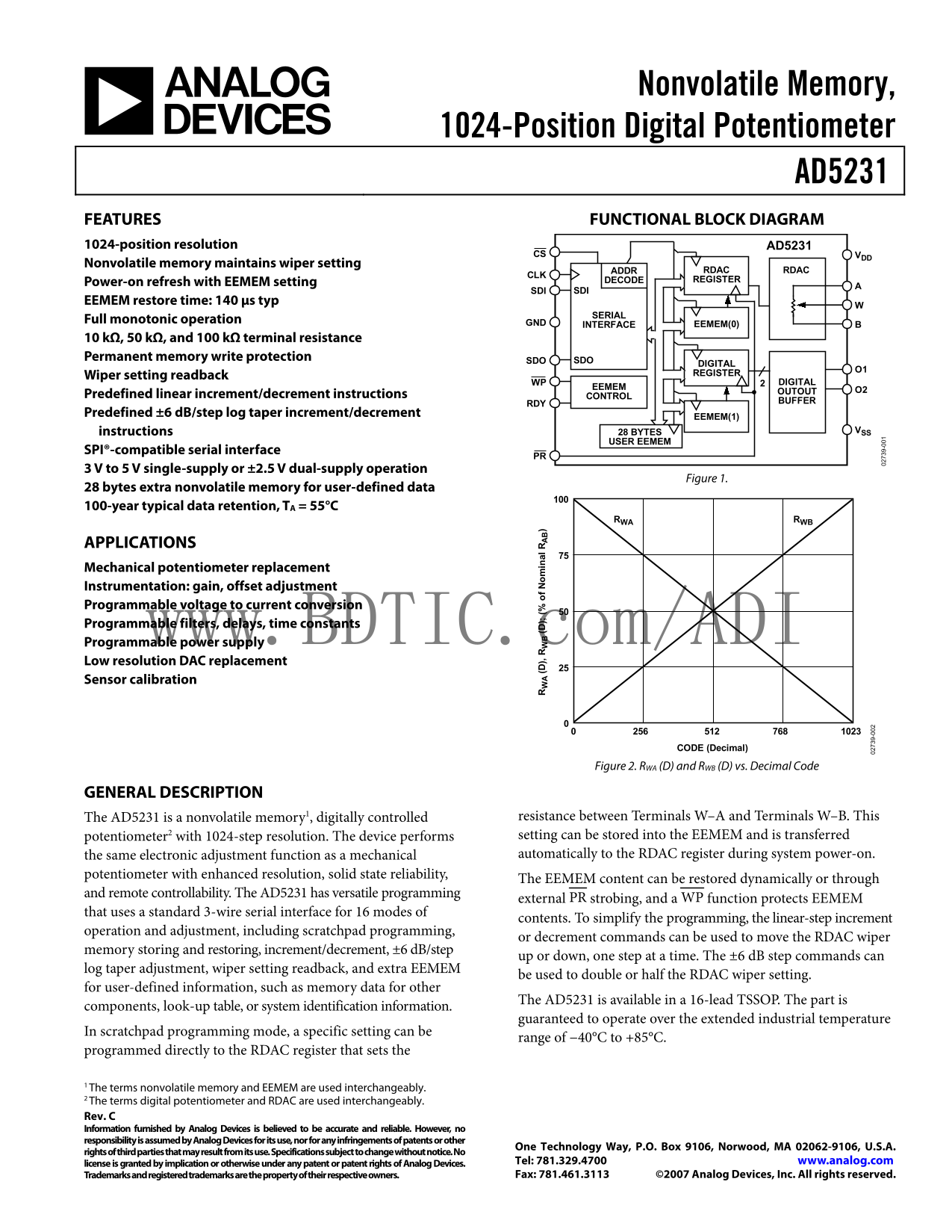
Figure 2. RWA (D) and RWB (D) vs. Decimal Code

GENERAL DESCRIPTION

The AD5231 is a nonvolatile memory1, digitally controlled resistance between Terminals W–A and Terminals W–B. This potentiometer2 with 1024-step resolution. The device performs setting can be stored into the EEMEM and is transferred the same electronic adjustment function as a mechanical automatically to the RDAC register during system power-on. potentiometer with enhanced resolution, solid state reliability, 9- The EEMEM content can be restored dynamically or through

and remote controllability. The AD5231 has versatile programming

external PR strobing, and a WP function protects EEMEM

that uses a standard 3-wire serial interface for 16 modes of

contents. To simplify the programming, the linear-step increment

operation and adjustment, including scratchpad programming,

or decrement commands can be used to move the RDAC wiper

memory storing and restoring, increment/decrement, ±6 d B/step

up or down, one step at a time. The ±6 d B step commands can

log taper adjustment, wiper setting readback, and extra EEMEM

be used to double or half the RDAC wiper setting.

for user-defined information, such as memory data for other

The AD5231 is available in a 16-lead TSSOP. The part is

components, look-up table, or system identification information.

guaranteed to operate over the extended industrial temperature

In scratchpad programming mode, a specific setting can be

range of −40°C to +85°C.

programmed directly to the RDAC register that sets the

1 The terms nonvolatile memory and EEMEM are used interchangeably.

2 The terms digital potentiometer and RDAC are used interchangeably.

Rev. C Information furnished by Analog Devices is believed to be accurate and reliable. However, no responsibility is assumed by Analog Devices for its use, nor for any infringements of patents or other

One Technology Way, P.O. Box 9106, Norwood, MA 02062-9106, U.S.A.

rights of third parties that may result from its use. Specifications subject to change without notice. No

license is granted by implication or otherwise under any patent or patent rights of Analog Devices. Tel: 781.329.4700 www.analog.com Trademarks and registered trademarks are the property of their respective owners. Fax: 781.461.3113 ©2007 Analog Devices, Inc. All rights reserved.

Page Summary Contents For AD5231 Analog Devices Data Sheet

Page 1 Nonvolatile Memory, 1024-Position Digital Potentiometer AD5231 FEATURES FUNCTIONAL BLOCK DIAGRAM 1024-position resolution AD5231 CS VDD Nonvolatile memory maintains wiper setting ADDR RDAC RDACCLK DEC...
Page 2 AD5231 TABLE OF CONTENTS Features Latched Digital Outputs Applications....................................................................................... Advanced Control Modes Functional Block Di...
Page 3 AD5231 SPECIFICATIONS ELECTRICAL CHARACTERISTICS—10 kΩ, 50 kΩ, 100 kΩ VERSIONS VDD = 3 V ± 10% or 5 V ± 10%, VSS = 0 V, VA = VDD, VB = 0 V, −40°C < TA < +85°C, unless otherwise noted. Table 1. P...
Page 4 AD5231 Parameter Symbol Conditions Min Typ1 Max Unit POWER SUPPLIES Single-Supply Power Range VDD VSS = 0 V 2.7 5.5 V Dual-Supply Power Range VDD/VSS ±2.25 ±2.75 V Positive Supply Current IDD VIH = VD...
Page 5 AD5231 TIMING CHARACTERISTICS—10 kΩ, 50 kΩ, 100 kΩ VERSIONS VDD = 3 V to 5.5 V, VSS = 0 V, and −40°C < TA < +85°C, unless otherwise noted. Table 2. Parameter Symbol Conditions Min Typ1 Max Unit ...
Page 6 AD5231 Timing Diagrams CPHA = 1 CS t12 CLK t5 B23 B0 CPOL = 1 t4 HIGH HIGH OR LOW OR LOW SDI B23–MSB B0–LSB SDO B24* B23–MSB B0–LSB *NOT DEFINED, BUT NORMALLY LSB OF CHARACTER PREVIOUSLY TRANSMITTED. ...
Page 7 AD5231 ABSOLUTE MAXIMUM RATINGS TA = 25°C, unless otherwise noted. Table 3. Stresses above those listed under Absolute Maximum Ratings may cause permanent damage to the device. This is a stress Parame...
Page 8 AD5231 PIN CONFIGURATION AND FUNCTION DESCRIPTIONS O1 O2 CLK RDY SDI CS SDO AD5231 PR TOP VIEW GND (Not to Scale) WP VSS VDD Figure 5. Pin Configuration Table 4. Pin Function Descriptions Pin No. Mnem...
Page 9 AD5231 -IN (L SB ER (L SB IN ER (L SB TYPICAL PERFORMANCE CHARACTERISTICS 1.5 2.0 VDD = 5V, VSS = 0V TA = +85°C 1.5 1.0 TA = –40°C TA = +25°C –0.5R TA = +25°C TA = +85°C TA = –40°C CODE (Decimal) CODE...
Page 10 EN (µ AD5231 f–3d B = 37k Hz, RAB = 10kΩ VDD = 2.7V, VSS = 0V TA = 25°C –4 f–3d B = 44k Hz, RAB = 100kΩ –6 –8 f–3d B = 85k Hz, RAB = 50kΩ VA = 1m V rms –14 VDD/VSS = ±2.5V D = MIDSCALE –16 1k 10k 100k...
Page 11 AD5231 IN (d IN (d PS (– d B CODE = 0x200 VDD = 5V VA = 2.25V –10 0x100 VB = 0V 0x10 EXPECTED VALUE –40 0x08 MIDSCALE 0.5V/DIV 100µs/DIV FREQUENCY (Hz) Figure 18. Gain vs. Frequency vs. Code, RAB = 50...
Page 12 AD5231 VA = VB = OPEN TA = 25°C 5V/DIV CLK RAB = 10kΩ 5V/DIV RAB = 50kΩ 5V/DIV RAB = 100kΩ IDD* 2m A/DIV 4ms/DIV *SUPPLY CURRENT RETURNS TO MINIMUM POWER CONSUMPTION CODE (Decimal) IF INSTRUCTION 0 (N...
Page 13 AD5231 TEST CIRCUITS Figure 26 to Figure 35 define the test conditions used in the specifications. NC 5V VOUTOP279 VMS OFFSET GND OFFSET BIAS NC = NO CONNECT Figure 26. Resistor Position Nonlinearity ...
Page 14 AD5231 THEORY OF OPERATION BASIC OPERATION The AD5231 digital potentiometer is designed to operate as a true variable resistor replacement device for analog signals that The basic mode of setting the ...
Page 15 AD5231 DIGITAL INPUT/OUTPUT CONFIGURATION returns high, the serial data-word is decoded according to the instructions in Table 7. The command bits (Cx) control the All digital inputs are ESD-protected...
Page 16 AD5231 TERMINAL VOLTAGE OPERATION RANGE POWER-UP SEQUENCE The AD5231’s positive VDD and negative VSS power supplies Because there are diodes to limit the voltage compliance at the define the boundary ...
Page 17 AD5231 In Table 6, command bits are C0 to C3, address bits are A3 to A0, Data Bit D0 to Data Bit D9 are applicable to RDAC, and D0 to D15 are applicable to EEMEM. Table 6. AD5231 24-Bit Serial Data-Wo...
Page 18 AD5231 ADVANCED CONTROL MODES makes the left-shift function as ideal a logarithmic adjustment as possible. The AD5231 digital potentiometer includes a set of user programming features to address the w...
Page 19 AD5231 Using Additional Internal Nonvolatile EEMEM The AD5231 contains additional user EEMEM registers for storing any 16-bit data such as memory data for other compo- SW(2N–1) nents, look-up tables, ...
Page 20 (D (D f N om in al AD5231 The general transfer equation for this operation is RWBRWA +× RRDDR (2) WABWB For example, the output resistance values in Table 12 are set for the RDAC latch codes with VDD ...
Page 21 AD5231 PROGRAMMING EXAMPLES Table 17. Storing Additional User Data in EEMEM The following programming examples illustrate a typical SDI SDO Action sequence of events for various features of the AD5231...
Page 22 AD5231 Lifetime Specification (A117) at a specific junction temperature FLASH/EEMEM RELIABILITY (TJ = 55°C). As part of this qualification procedure, the The Flash/EE memory array on the AD5231 is ful...
Page 23 AD5231 APPLICATIONS BIPOLAR OPERATION FROM DUAL SUPPLIES The AD5231 can be operated from dual supplies ±2.5 V, which OP2177AD5231 VO enables control of ground referenced ac signals or bipolar V– opera...
Page 24 AD5231 PROGRAMMABLE CURRENT SOURCE A programmable current source can be implemented with the AD8552AD5231 VO circuit shown in Figure 52. VOUTVIN –5V VIN 0V TO (2.048V + VL) +2.5VREF +5V –2.5VREF SLEEP...
Page 25 AD5231 PROGRAMMABLE BIDIRECTIONAL CURRENT RESISTANCE SCALING SOURCE The AD5231 offers 10 kΩ, 50 kΩ, and 100 kΩ nominal For applications that require bidirectional current control or resistance. For us...
Page 26 AD5231 RDAC CIRCUIT SIMULATION MODEL The following code provides a macro model net list for the 10 kΩ RDAC: The internal parasitic capacitances and the external load dominates the ac characteristics o...
Page 27 AD5231 OUTLINE DIMENSIONS 4.40 BSC 4.30 PIN 1 1.20 MAX 0.19 SEATING PLANE COPLANARITY 0.10 COMPLIANT TO JEDEC STANDARDS MO-153-AB Figure 58. 16-Lead Thin Shrink Small Outline Package [TSSOP] (RU-16) D...
Page 28 AD5231 NOTES www.BDTIC.com/ADI Purchase of licensed I2C components of Analog Devices or one of its sublicensed Associated Companies conveys a license for the purchaser under the Philips I2C Patent Rig...

Manual Details

Brand Analog Devices
Pages 28
File Size 732.38 KB
Published July 22, 2026
0 views

Enter the captcha to get the download link:

captcha

Frequently Asked Questions

How is the wiper setting maintained during power cycles?

The nonvolatile memory (EEMEM) maintains the wiper setting, which is restored automatically upon system power-on.

What electrical supply options does the device support?

It supports 3 V to 5 V single-supply or ±2.5 V dual-supply operation.

How do I perform fine-grained resistance adjustments?

You can use linear-step, log taper adjustment (±6 dB/step), and scratchpad programming modes for precise control.

What is the guaranteed operating temperature range?

The AD5231 guarantees operation over an extended industrial temperature range of −40°C to +85°C.