Page 1
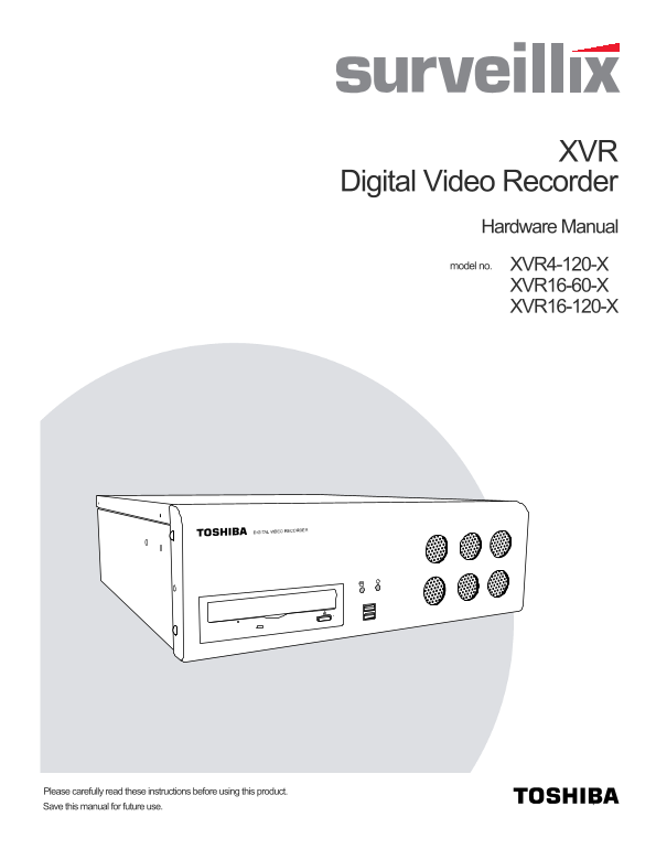
Digital Video Recorder Hardware Manual XVR4-120-Xmodel no. XVR16-60-X XVR16-120-X Please carefully read these instructions before using this product. Save this manual for future use.
Page 2
Surveillix™ XVR Hardware Manual Manual Edition 27811AD – APRIL 2007 Printed in USA No part of this documentation may be reproduced in any means, electronic or mechanical, for any purpose, except as ex...
Page 3
LIMITED WARRANTY DIGITAL VIDEO RECORDER The Imaging Systems Division of Toshiba America Information Systems, Inc. ("ISD") makes the following limited warranties. These limited warranties ext...
Page 4
IMPORTANT SAFEGUARDS 1. Read Owner’s Manual – After unpacking this product, read the owner’s manual carefully, and follow all the operating and other instruction 2. Power Sources – This product should...
Page 5
IMPORTANT SAFEGUARDS, continued 15. Damage Requiring Service – Unplug the unit from the outlet and refer servicing to qualified service personnel under the following conditions: When the power-supply ...
Page 6
NOTES ON CLEANING Use a soft dry cloth for cleaning. For stubborn dirt, soak the cloth in a weak detergent solution, wring well and wipe. Use a dry cloth to wipe it dry. Do not use any type of solvent...
Page 7
WARNING TO REDUCE THE RISK OF ELECTRICAL SHOCK, DO NOT EXPOSE THIS APPLIANCE TO RAIN OR MOISTURE. DANGEROUS HIGH VOLTAGES ARE PRESENT INSIDE THE ENCLOSURE. DO NOT OPEN THE CABINET. REFER SERVICING TO ...
Page 8
RACK MOUNT INSTRUCTIONS Elevated Operating Ambient – If installed in a closed or multi-unit rack assembly, the operating ambient temperature of the rack environment may be greater than room ambient. T...
Page 9
- ix -
Page 11
Table of Contents PREFACE..................................................................................................................................................................................
Page 12
- xii -
Page 13
PREFACE ABOUT THIS GUIDE This manual is a setup and maintenance guide that can be used for reference when setting up the XVR unit and for troubleshooting when a problem occurs. Only authorized personn...
Page 15
INTRODUCTION PRODUCT DESCRIPTION A Surveillix XVR is simply a server that performs as a High Definition Digital Recorder. By utilizing the many features of a computer, including processing power, stor...
Page 16
FEATURES Toshiba’s Surveillix XVRs include the following new features: • Optimized and Designed for Microsoft Windows XP Embedded • Record up to 120 PPS • Up to 16 Camera Inputs • Supports up to 4 Rel...
Page 17
NOTES:
Page 18
NOTES:
Page 19
CONTROLS AND CONNECTIONS This chapter includes the following information: • Input / Output Connector Locations • Front Panel Controls and LEDs • Rear Panel Connectors
Page 20
SYSTEM SPECIFICATIONS Surveillix™ state-of-the-art High Definition Digital Recorders are housed in a high performance and versatile 3U Rack-Mount case allowing easy storage of multiple XVRs for enterp...
Page 21
FRONT PANEL CONTROLS AND LEDS The front panel of the XVR unit contains the devices that will be commonly used for data removal, retrieval, and backup replacement. The most common components and button...
Page 22
REAR PANEL CONNECTORS The rear panel of the XVR unit contains the connectors used to attach cameras, sensors, and relays to the XVR. Below are diagrams that outline the location and description of eac...
Page 23
4 Channel BNC Connectors for Video Input Audio/Spot Monitor Output AC Power Connector RJ-45 Network Jack Cooling Fan PS/2 Mouse Input Sensors & Control Outputs PS/2 Keyboard Input RS-422 Interface...
Page 24
NOTES:
Page 25
GETTING STARTED This chapter includes the following information: • Included Components • Setting the XVR Hardware • Optional Components
Page 26
IDENTIFYING INCLUDED COMPONENTS Surveillix™ XVRs come with a mouse, keyboard and selected software and cables. Identify the following components to make sure everything has been properly included with...
Page 27
OPTIONAL COMPONENTS To fully utilize the XVR unit’s potential; several optional Surveillix components are listed below. Contact the dealer for more information. 1 GB-NIC Gigabit Network Card Increase ...
Page 28
KEYBOARD SETUP To attach the keyboard to the XVR unit, plug the end of the Keyboard into the keyboard PS/2 Port located on the back of the machine. The keyboard PS/2 Port can be identified by the purp...
Page 29
MONITOR SETUP The XVR has the following connection available to attach a monitor. SVGA Output To VGA Monitor. Attach the monitor or monitors to the rear of the XVR unit using the cable supplied by the...
Page 30
CONNECTING A VIDEO SOURCE TO THE XVR There are different types of Video Sources that can be plugged into the XVR unit including DVD players, VHS players, and CCTV Cameras. The back of the XVR unit con...
Page 31
CONNECTING SENSORS TO THE XVR Each XVR unit may have up to 16 Sensor inputs. These inputs can be used with devices such as infrared devices, motion device, glass breakage alarms, door and window trips...
Page 32
CONNECTING CONTROL OUTPUTS TO THE XVR Each XVR unit may have up to 4 Control Outputs. These outputs can be used to trigger devices such as Sirens, Phone Dialers, Lights, and any other relay activated ...
Page 33
LOOPING OUTPUTS The 16 Channel XVR unit may have up to 16 Looping outputs. Depending on the destination of the outputs, each output may have to be terminated. The outputs are located on the BNC Connec...
Page 34
CONNECTING A PTZ CAMERA Setting up a PTZ Camera is simple. The XVR unit comes preassembled with an internal PTZ adapter. The cabling may be run up to 4,000 ft using 22 Gauge Twisted Pair. It is import...
Page 35
TURNING ON THE XVR 1. Turn on the monitor and any external peripherals (ex. Printers, External Storage Devices, etc.) connected to the XVR unit. 2. Turn on the Power Switch located in the rear of the ...