Roland VR-700 Stage Keyboard MIDI Implementation User's Manual
Summary
This technical manual provides an exhaustive guide to the MIDI implementation specifications for the VR-700 synthesizer. It details how core functions—including Note On/Off, Volume, Modulation, Resonance, Bank Selection, and Timbre control parameters (like Attack and Cutoff)—are transmitted across various MIDI channels and physical inputs (MIDI IN and PEDAL IN). Designed for musicians, audio engineers, and professional sound designers, this resource ensures precise knowledge of the system's compatibility, enabling complex integration and perfect electronic sound performance in studio or live settings.
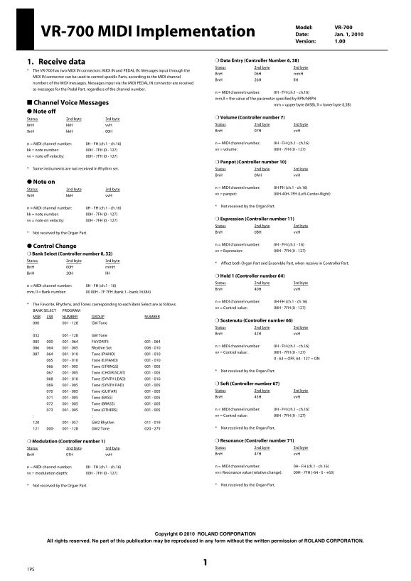
Page 1 Text Content
Model: VR-700 VR-700 MIDI Implementation Date: Jan. 1, 2010 Version: 1.00
❍ Data Entry (Controller Number 6, 38)
1. Receive data
Status 2nd byte 3rd byte
The VR-700 has two MIDI IN connectors: MIDI IN and PEDAL IN. Messages input through the
Bn H 06H mm H
MIDI IN connector can be used to control specific Parts, according to the MIDI channel
Bn H 26H ll H
numbers of the MIDI messages. Messages input via the MIDI PEDAL IN connector are received as messages for the Pedal Part, regardless of the channel number.
n = MIDI channel number: 0H - FH (ch.1 - ch.16) mm,ll = the value of the parameter specified by RPN/NRPN
■ Channel Voice Messages mm = upper byte (MSB), ll = lower byte (LSB) ● Note off
Status 2nd byte 3rd byte ❍ Volume (Controller number 7) 8n H kk H vv H Status 2nd byte 3rd byte 9n H kk H 00H Bn H 07H vv H
n = MIDI channel number: 0H - FH (ch.1 - ch.16) n = MIDI channel number: 0H - FH (ch.1 - ch.16) kk = note number: 00H - 7FH (0 - 127) vv = volume: 00H - 7FH (0 - 127)
vv = note off velocity: 00H - 7FH (0 - 127)
❍ Panpot (Controller number 10)
Some instruments are not received in Rhythm set. Status 2nd byte 3rd byte
Bn H 0AH vv H
● Note on
n = MIDI channel number: 0H-FH (ch.1 - ch.16)
Status 2nd byte 3rd byte
vv = panpot: 00H-40H-7FH (Left-Center-Right)
9n H kk H vv H
Not received by the Organ Part.
n = MIDI channel number: 0H - FH (ch.1 - ch.16) kk = note number: 00H - 7FH (0 - 127)
vv = note on velocity: 00H - 7FH (0 - 127) ❍ Expression (Controller number 11) Status 2nd byte 3rd byte Not received by the Organ Part. Bn H 0BH vv H
n = MIDI channel number: 0H - FH (ch.1 - 16)
● Control Change
vv = Expression: 00H - 7FH (0 - 127)
❍ Bank Select (Controller number 0, 32)
Status 2nd byte 3rd byte
Affect both Organ Part and Ensemble Part, when receive in Controller Part.
Bn H 00H mm H Bn H 20H ll H
❍ Hold 1 (Controller number 64) Status 2nd byte 3rd byte
n = MIDI channel number: 0H - FH (ch.1 - 16)
Bn H 40H vv H
mm, ll = Bank number: 00 00H - 7F 7FH (bank.1 - bank.16384)
n = MIDI channel number: 0H-FH (ch.1 - ch.16)
The Favorite, Rhythms, and Tones corresponding to each Bank Select are as follows.
vv = Control value: 00H - 7FH (0 - 127)
BANK SELECT PROGRAM MSB LSB NUMBER GROUP NUMBER
❍ Sostenuto (Controller number 66)
001 - 128 GM Tone
Status 2nd byte 3rd byte Bn H 42H vv H
001 - 128 GM Tone 001 - 064 FAVORITE 001 - 064
n = MIDI channel number: 0H - FH (ch.1 - ch.16)
001 - 005 Rhythm Set 006 - 010
vv = Control value: 00H - 7FH (0 - 127)
001 - 010 Tone (PIANO) 001 - 010
0 - 63 = OFF, 64 - 127 = ON
001 - 010 Tone (E.PIANO) 001 - 010 001 - 005 Tone (STRINGS) 001 - 005
Not received by the Organ Part.
001 - 005 Tone (CHOIR/SCAT) 001 - 005 001 - 010 Tone (SYNTH LEAD) 001 - 010
001 - 005 Tone (SYNTH PAD) 001 - 005 ❍ Soft (Controller number 67) 001 - 005 Tone (GUITAR) 001 - 005 Status 2nd byte 3rd byte 001 - 005 Tone (BASS) 001 - 005 Bn H 43H vv H
001 - 005 Tone (BRASS) 001 - 005
001 - 005 Tone (OTHERS) 001 - 005 n = MIDI channel number: 0H - FH (ch.1 - ch.16) vv = Control value: 00H - 7FH (0 - 127)
001 - 057 GM2 Rhythm 011 - 019
000- 001 - 128 GM2 Tone 020 - 275 Not received by the Organ Part.
❍ Modulation (Controller number 1) ❍ Resonance (Controller number 71) Status 2nd byte 3rd byte Status 2nd byte 3rd byte Bn H 01H vv H Bn H 47H vv H
n = MIDI channel number: 0H - FH (ch.1 - ch.16) n = MIDI channel number: 0H - FH (ch.1 - ch.16) vv = modulation depth: 00H - 7FH (0 - 127) vv= Resonance value (relative change): 00H - 7FH (-64 - 0 - +63)
Not received by the Organ Part. Not received by the Organ Part.
Copyright © 2010 ROLAND CORPORATION
All rights reserved. No part of this publication may be reproduced in any form without the written permission of ROLAND CORPORATION.
Page Summary Contents For Roland VR-700 Stage Keyboard MIDI Implementation User's Manual
Manual Details
| Brand | Roland |
|---|---|
| Pages | 11 |
| File Size | 220.72 KB |
| Published | June 02, 2026 |
Enter the captcha to get the download link:

Frequently Asked Questions
How are MIDI messages input via the PEDAL IN connector used?
Messages received through the PEDAL IN connector are always treated as messages for the Pedal Part, regardless of the assigned channel number.
What does a "Control Change" message do and what is its range?
The Control Change message uses Controller number 11 (Expression) or specific controllers for other parameters and has a value range of 00H - 7FH (0 - 127).
Does the Organ Part receive all types of MIDI controls?
No, certain controls are not received by the Organ Part, such as Panpot, Expression, Resonance, etc.
What is the format for Bank Select messages?
Bank Select uses Controller number 0 (32) and requires two status bytes (BnH 00H mmH BnH 20H llH).
How many MIDI channels does this device support?
The device supports 16 MIDI channels, numbered from 0H to FH (ch.1 - ch.16).