Roland V-Drums TD-50K2 V-Drums Setup Guide User Manual
Summary
Comprehensive setup guide for assembling the professional TD-50K2 electronic drum kit system. This manual provides detailed, step-by-step instructions on stand mounting, hi-hat assembly, cymbal placement, and connecting all peripheral components including toms and kick pedals. It is essential for musicians who are setting up or maintaining a modular electronic drumming station, ensuring safe and correct operation of the full kit setup.
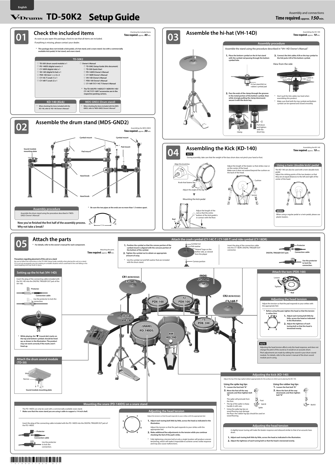
Page 1 Text Content
Assembly and connections
TD-50K2 Setup Guide Time required: approx. 150 min.
© 2021 Roland Corporation
Checking the included items Assembling the VH-14D
Check the included items Assemble the hi-hat (VH-14D)
Time required: approx. 40 min. Time required: approx. 10 min.
As soon as you open the package, check to see that all items are included. If anything is missing, please contact your dealer.
Assembly procedure
* This package does not include a kick pedal, a hi-hat stand, and a snare stand. Use with a commercially Assemble the stand using the procedure described in “VH-14D Owner’s Manual.” available kick pedal, hi-hat stand, and snare stand.
1. Place the bottom cymbal on the hi-hat stand 3. Connect the link cables A/B on the top cymbal to with the cymbal rod passing through the bottom the link jacks A/B of the bottom cymbal.
TD-50K2
cymbal hole.
TD-50X (drum sound module) x 1 Owner’s Manual
View from the side
PD-140DS (digital snare) x 1 TD-50K2 Setup Guide (this document) CY-18DR (digital ride) x 1 TD-50X Quick Start VH-14D (digital hi-hat) x 1 PD-140DS Owner’s Manual PDX-100 (tom 1, 2, 3) x 3 CY-18DR Owner’s Manual
CY-14C-T (crash 1) x 1 VH-14D Owner’s Manual Cable in Cable in
CY-16R-T (crash 2) x 1 PDX-100 Owner’s Manual
CY-16R-T/CY-14C-T Owner’s Manual
Hi-hat stand felt (or rubber) cymbal pad
* The TD-50X/PD-140DS/CY-18DR/VH-14D/ CY-14C-T/CY-16R-T accessories are in the
respective packing cartons. 2. Pass the ends of the clamp through the grooves in the metal portion of the bottom cymbal, then * Don’t pull the link cables too hard when while strongly pulling the clamp downward, assembling this product. secure it with the drum key.
* Make sure that both the top cymbal and bottom
KD-140 (Kick) MDS-GND2 (Drum stand)
cymbal can be opened and closed smoothly.
* When checking the items included with the * When checking the items included with the MDS-
KD-140, refer to “KD-140 Owner’s Manual.” GND2, refer to “MDS-GND2 Owner’s Manual.”
Assemble the drum stand (MDS-GND2)
Pull down and tighten
Assembling the MDS-GND2
with the
Time required: approx. 30 min.
drum key.Clamp
Cymbal mount Cymbal mount
Pad mount Assembling the KD-140
Sound module Assembling the Kick (KD-140)
Time required: approx. 10 min.
mounting plate Pad mount
NOTE During assembly, take care that the weight of the bass drum does not pinch your hand or foot.
Adjust the length of the beater so that strikes near or Using a twin (double kick) pedal Align the knotches
on the center of the head.
The KD-140 can also be used with a twin (double kick)
Make sure it does not extend beyond the cushion on
pedal.
the back of the head.
Adjust the striking points of the two beaters so that
Hand knob
they are at equal distances to the left and right of the center of the head.
Cushion
Knob that fastens leg
Adjust the angle of the leg
Sensor
Hand knob
Mounting the kick pedal
* Be sure the two pipes at the ends are no more than 1.5 meters apart.
Assembly procedure
Adjust the length of the MEMO Assemble the drum stand using the procedure described in “MDS- rod so that the entire
When using a regular pedal or a twin pedal, please use
GND2 Owner’s Manual.” bottom of the kick pedal is
plastic beaters.
in contact with the floor.
Now you’ve finished the first half of the assembly process.
Why not take a break?
Attach the parts Attach the crash cymbal (CY-14C-T / CY-16R-T) and ride cymbal (CY-18DR)
Cymbal nut
* For details, refer to the owner’s manual for each component.
1. Position the cymbal so that the convex portion of the Insert the plug of the connection cable Protector
Felt washer
cymbal mount is aligned with the concave portion of into the CY-18DR’s DIGITAL TRIGGER OUT
Attaching the parts “Roland” logo on the connector.
the bottom of the cymbal.
farther side, as viewed Connection cable
Time required: approx. 40 min. 2. Tighten the cymbal nut to obtain an appropriate DIGITAL TRIGGER OUT jack
from the player
amount of sway.
Precautions regarding placement of this unit on a stand
* Use the cymbal nut and felt washer that are included
Use the protector
Be sure to follow the instructions in the TD-50K2 Setup Guide carefully when placing this unit on a stand. Convex portion
with the drum stand.
If it is not set up properly, you risk creating an unstable situation which could lead to the unit falling or the to lock the
stand toppling, and may result in injury. connection.
Attach the tom (PDX-100)
Setting up the hi-hat (VH-14D)
(RIDE)
CR1 (BOW/EDGE) Loosen
Insert the plug of the connecting cable included with
CY-18DR
the VH-14D into the DIGITAL TRIGGER OUT jack of the CY-14C-T VH-14D.
Tighten
Protector
Connection cable CR2 (BOW/EDGE)
Use the protector to lock the Adjusting the head tension connection. PDX-100 CY-16R-TPDX-100
Adjust the tension so that the pad responds to your strikes with the appropriate feel.
* Before using the pad, tighten the head so that the tension is rather firm.
(HI-HAT) 1. Adjust each tuning bolt little by little, across the head as indicated
VH-14D T3
in the illustration.
PDX-100 2. Adjust the tightness of each
(SNARE) tuning bolt so that the head is tensioned evenly.
PD-140DS
TD-50X
* While playing, the “7” (round dot) marks on
KD-140
the top and bottom cymbals should be lined up, as shown in the illustration. The product may not work correctly if the marks aren’t NOTE lined up.
Adjusting the head tension affects only the head response, and does not change the pitch of the sound as it would on an acoustic drum. Pitch adjustments are made by editing the sound in your drum sound module. For details, refer to the owner’s manual of the drum sound module you’re using.
Attach the drum sound module (TD-50)
Adjusting the kick (KD-140)
Narrow Adjust the tip of the legs (spike/rubber) appropriately for the surface on which you’re placing the KD-140.
Using the spike leg tips Using the rubber leg tips 1. Loosen the foot bolt “B.” 1. Loosen the foot bolt “B.”
Sound module mounting plate 2. Move the foot all the way 2. Move the foot all the way
upward, and then tighten bolt downward, and then tighten “B.” bolt “B.”
The spike will protrude from
the foot. Mounting the snare (PD-140DS) on a snare stand * The tip of the spike is sharp; Bolt B
Bolt B
handle it with care.
Spike
The PD-140DS can only be used with a commercially available snare stand. * Using the spike leg tips on
* Make sure that the snare stand you are using is able to support a 14-inch shell. Adjusting the head tension wood flooring may damage the floor; the rubber leg tips should be used on Adjust the tension so that the pad responds to your strikes with the appropriate feel. wood flooring.
1. Adjust each tuning bolt little by little, across the head as indicated in the
Insert the plug of the connecting cable included with the PD-140DS into the DIGITAL TRIGGER OUT jack of illustration. the PD-140DS. Adjusting the head tension
Adjust the tension so that the pad responds to your strikes with the appropriate feel.
A slightly looser tuning will make the beater response and rebound similar to that of an acoustic bass
Protector
2. Make additional fine adjustments to the tension while you continue drum.
checking the feel of the pad’s strike.
Connection cable 1. Adjust each tuning bolt little by little, across the head as indicated in the illustration.
* Fully tightening a tension bolt at only a single location will produce uneven
tensioning, which will make it impossible to achieve correct strike response 2. Adjust the tightness of each tuning bolt so that the head is tensioned evenly.
Use the protector
and may also cause malfunctions.
to lock the connection.
Page Summary Contents For Roland V-Drums TD-50K2 V-Drums Setup Guide User Manual
Manual Details
| Brand | Roland |
|---|---|
| Pages | 2 |
| File Size | 3.32 MB |
| Published | June 01, 2026 |
Enter the captcha to get the download link:

Frequently Asked Questions
What equipment is NOT included in this package?
A kick pedal, hi-hat stand, or snare stand must be used with commercially available accessories.
How should I assemble the drum stand (MDS-GND2)?
Refer to the separate 'MDS-GND2 Owner’s Manual' for assembly instructions. Caution: Keep electronics away from wet environments and extreme heat.
What precautions must be taken when setting up the unit on a stand?
Ensure the setup is proper, as improper placement could lead to unstable situations, falling, or injury. Never climb on top of the unit.
How do I properly attach crash or ride cymbals?
Position the cymbal so its convex portion aligns with the concave portion of the mount. Use the included felt washer and tighten the nut appropriately.