Roland V-Drums Acoustic Design - English VAD306 Setup Guide
Summary
Master your modular drumming experience with this comprehensive setup guide. This manual provides detailed, step-by-step instructions for connecting all electronic drum pads, stands, and the central sound module unit. It is essential reading for musicians who require professional assembly guidance to ensure system stability, proper component linkage, and optimal performance right out of the box.
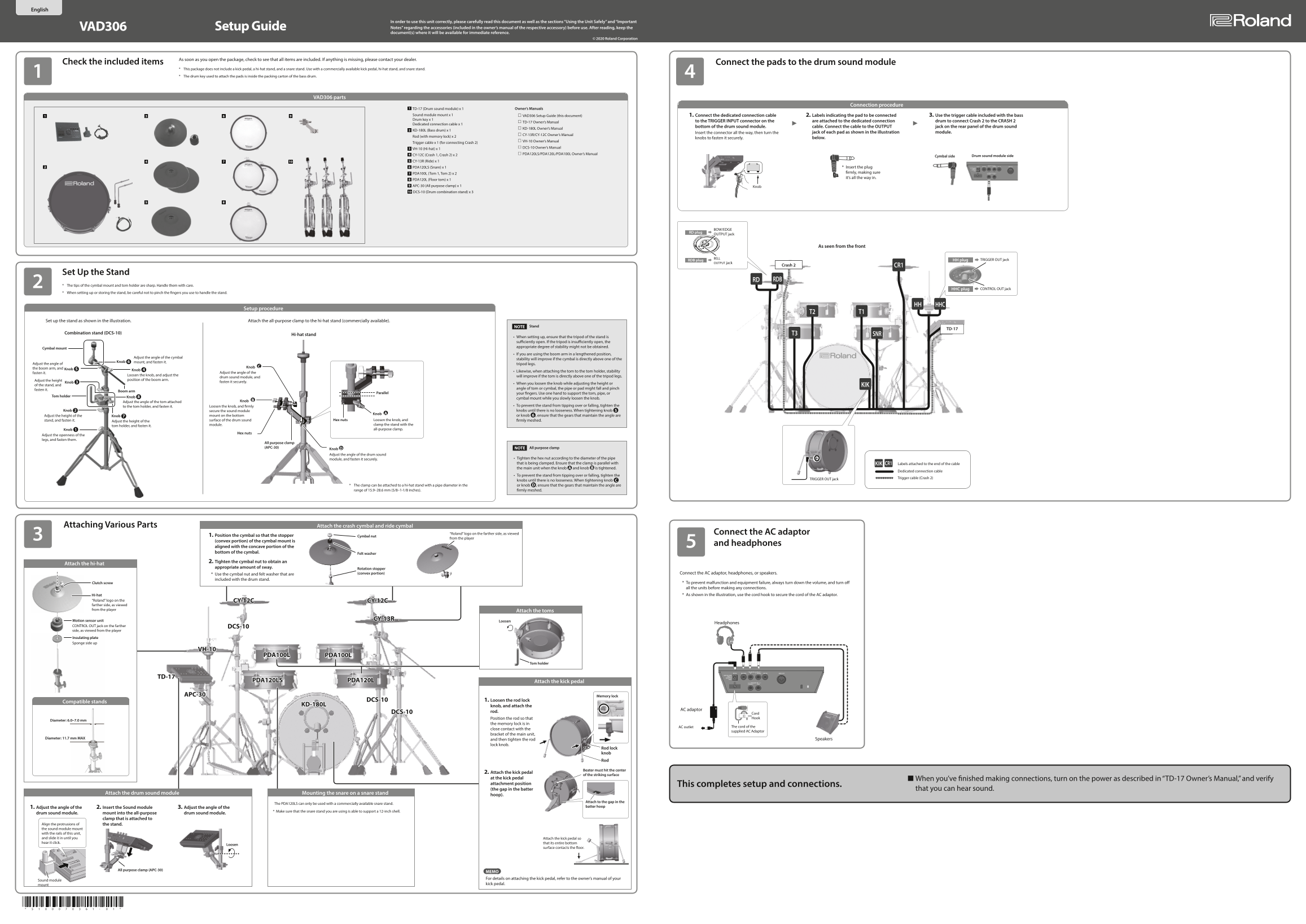
Page 1 Text Content
In order to use this unit correctly, please carefully read this document as well as the sections “Using the Unit Safely” and “Important VAD306 Setup Guide Notes” regarding the accessories (included in the owner’s manual of the respective accessory) before use. After reading, keep the document(s) where it will be available for immediate reference.
© 2020 Roland Corporation
As soon as you open the package, check to see that all items are included. If anything is missing, please contact your dealer.
Check the included items Connect the pads to the drum sound module
* This package does not include a kick pedal, a hi-hat stand, and a snare stand. Use with a commercially available kick pedal, hi-hat stand, and snare stand. * The drum key used to attach the pads is inside the packing carton of the bass drum.
VAD306 parts
Connection procedure
TD-17 (Drum sound module) x 1 Owner’s Manuals
Sound module mount x 1 VAD306 Setup Guide (this document) 1. Connect the dedicated connection cable 2. Labels indicating the pad to be connected 3. Use the trigger cable included with the bass Drum key x 1
TD-17 Owner’s Manual to the TRIGGER INPUT connector on the are attached to the dedicated connection drum to connect Crash 2 to the CRASH 2
Dedicated connection cable x 1
bottom of the drum sound module. cable. Connect the cable to the OUTPUT jack on the rear panel of the drum sound
KD-180L Owner’s Manual
KD-180L (Bass drum) x 1
Insert the connector all the way, then turn the jack of each pad as shown in the illustration module.
CY-13R/CY-12C Owner’s Manual
Rod (with memory lock) x 2
knobs to fasten it securely. below.
VH-10 Owner’s Manual
Trigger cable x 1 (for connecting Crash 2)
DCS-10 Owner’s Manual
VH-10 (Hi-hat) x 1
CY-12C (Crash 1, Crash 2) x 2 PDA120LS/PDA120L/PDA100L Owner’s Manual
Cymbal side Drum sound module side
CY-13R (Ride) x 1
PDA120LS (Snare) x 1 * Insert the plug PDA100L (Tom 1, Tom 2) x 2 firmly, making sure it’s all the way in.
PDA120L (Floor tom) x 1 APC-30 (All purpose clamp) x 1 Knob DCS-10 (Drum combination stand) x 3
BOW/EDGE
RD plug
OUTPUT jack
As seen from the front
RDB plug HH plug TRIGGER OUT jack
OUTPUT jack
Crash 2 CR1
Set Up the Stand
RD RDB
* The tips of the cymbal mount and tom holder are sharp. Handle them with care.
HHC plug CONTROL OUT jack
* When setting up or storing the stand, be careful not to pinch the fingers you use to handle the stand.
HH HHC
Setup procedure
Set up the stand as shown in the illustration. Attach the all-purpose clamp to the hi-hat stand (commercially available).
NOTE Stand
TD-17
Combination stand (DCS-10) T3
Hi-hat stand SNR
When setting up, ensure that the tripod of the stand is sufficiently open. If the tripod is insufficiently open, the appropriate degree of stability might not be obtained.
Cymbal mount
If you are using the boom arm in a lengthened position,
Adjust the angle of the cymbal
stability will improve if the cymbal is directly above one of the
Knob 6 mount, and fasten it.
Adjust the angle of tripod legs.
the boom arm, and Knob C
Knob 5 Knob 4
Likewise, when attaching the tom to the tom holder, stability
fasten it. Adjust the angle of the
Loosen the knob, and adjust the
drum sound module, and will improve if the tom is directly above one of the tripod legs.
Adjust the height position of the boom arm.
Knob 3 fasten it securely.
When you loosen the knob while adjusting the height or
of the stand, and KIK
angle of tom or cymbal, the pipe or pad might fall and pinch
fasten it.
Boom arm
Parallel your fingers. Use one hand to support the tom, pipe, or
Tom holder Knob 8
cymbal mount while you slowly loosen the knob.
Adjust the angle of the tom attached Knob B
to the tom holder, and fasten it. Loosen the knob, and firmly To prevent the stand from tipping over or falling, tighten the
Knob 2 secure the sound module knobs until there is no looseness. When tightening knob 5
Knob A
Adjust the height of the Knob 7 mount on the bottom or knob 6 , ensure that the gears that maintain the angle are
stand, and fasten it. surface of the drum sound Hex nuts Loosen the knob, and firmly meshed.
Adjust the height of the
module. clamp the stand with the
tom holder, and fasten it.
Knob 1 all-purpose clamp.
Hex nuts
Adjust the openness of the legs, and fasten them.
All purpose clamp (APC-30) NOTE All purpose clamp
Knob D Adjust the angle of the drum sound
module, and fasten it securely. Tighten the hex nut according to the diameter of the pipe that is being clamped. Ensure that the clamp is parallel with KIK Labels attached to the end of the cable CR1 the main unit when the knob A and knob B is tightened.
Dedicated connection cable
To prevent the stand from tipping over or falling, tighten the
Trigger cable (Crash 2)
TRIGGER OUT jack
knobs until there is no looseness. When tightening knob C
* The clamp can be attached to a hi-hat stand with a pipe diameter in the or knob D , ensure that the gears that maintain the angle are range of 15.9–28.6 mm (5/8–1-1/8 inches). firmly meshed.
Attaching Various Parts Attach the crash cymbal and ride cymbal
“Roland” logo on the farther side, as viewed Connect the AC adaptor
1. Position the cymbal so that the stopper Cymbal nut
from the player
(convex portion) of the cymbal mount is
and headphones
aligned with the concave portion of the bottom of the cymbal.
Felt washer
2. Tighten the cymbal nut to obtain an
Attach the hi-hat
appropriate amount of sway.
Rotation stopper
* Use the cymbal nut and felt washer that are (convex portion) Connect the AC adaptor, headphones, or speakers.
included with the drum stand.
Clutch screw * To prevent malfunction and equipment failure, always turn down the volume, and turn off all the units before making any connections. Hi-hat * As shown in the illustration, use the cord hook to secure the cord of the AC adaptor.
“Roland” logo on the CY-12C CY-12C farther side, as viewed from the player
Attach the toms
Motion sensor unit CY-13R
Loosen
Headphones
CONTROL OUT jack on the farther DCS-10 side, as viewed from the player Insulating plate Sponge side up
VH-10
PDA100L PDA100L
Tom holder
TD-17
PDA120LS PDA120L Attach the kick pedal
APC-30 Memory lock
DCS-10 1. Loosen the rod lock
Compatible stands
KD-180L knob, and attach the
AC adaptor
DCS-10 rod.
Cord Position the rod so that Hook
Diameter: 6.0–7.0 mm
the memory lock is in
AC outlet The cord of the
close contact with the
supplied AC Adaptor
bracket of the main unit,
Diameter: 11.7 mm MAX Speakers
and then tighten the rod lock knob.
Rod lock knob Rod
Beater must hit the center
2. Attach the kick pedal
of the striking surface
at the kick pedal When you’ve finished making connections, turn on the power as described in “TD-17 Owner’s Manual,” and verify attachment position (the gap in the batter that you can hear sound.This completes setup and connections.
Attach the drum sound module Mounting the snare on a snare stand
hoop).
Attach to the gap in the
The PDA120LS can only be used with a commercially available snare stand.
1. Adjust the angle of the 2. Insert the Sound module 3. Adjust the angle of the batter hoop
* Make sure that the snare stand you are using is able to support a 12-inch shell.
drum sound module. mount into the all-purpose drum sound module.
clamp that is attached to
Align the protrusions of the stand. the sound module mount with the rails of this unit, and slide it in until you Attach the kick pedal so hear it click. that its entire bottom
Loosen
surface contacts the floor.
All purpose clamp (APC-30)
MEMO For details on attaching the kick pedal, refer to the owner’s manual of your
Sound module
mount kick pedal.
Page Summary Contents For Roland V-Drums Acoustic Design - English VAD306 Setup Guide
Manual Details
| Brand | Roland |
|---|---|
| Pages | 2 |
| File Size | 7.64 MB |
| Published | May 29, 2026 |
Enter the captcha to get the download link:

Frequently Asked Questions
Which guide should I keep after setting up the unit?
Keep the Setup Guide VAD306 document(s) for immediate reference.