Roland Roland V-Drums Acoustic Design VAD706
Summary
This comprehensive manual serves as your definitive guide for setting up, assembling, and calibrating the VAD706 electronic drum kit system. It walks through detailed procedures for connecting specialized pads (snare, toms, cymbals) and stands, guiding you on initial tuning adjustments and proper connections to the central sound module. Designed for musicians and enthusiasts, this guide ensures safe installation of all components, allowing you to immediately replicate the authentic feel of an acoustic drum while utilizing advanced digital sound features.
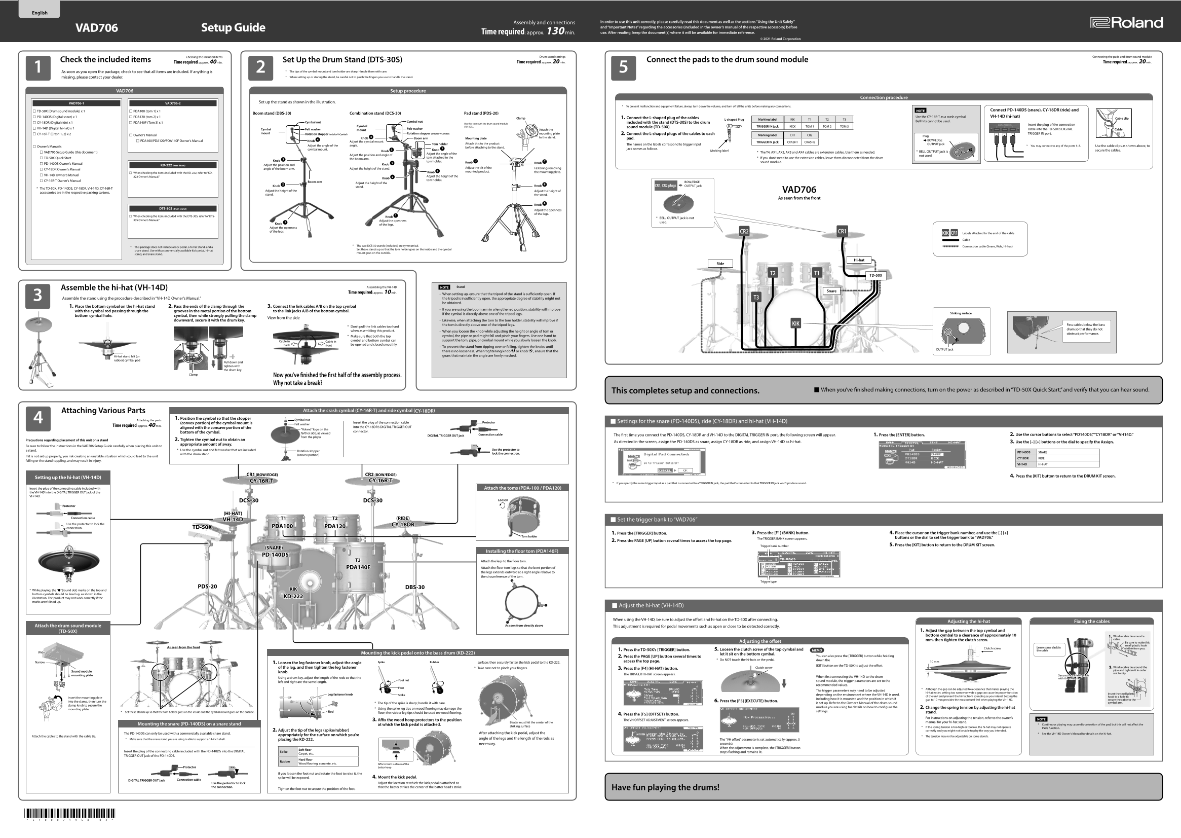
Page 1 Text Content
Assembly and connections In order to use this unit correctly, please carefully read this document as well as the sections “Using the Unit Safely” and “Important Notes” regarding the accessories (included in the owner’s manual of the respective accessory) before
VAD706 Setup Guide
Time required: approx. 130 min. use. After reading, keep the document(s) where it will be available for immediate reference.
© 2021 Roland Corporation
Checking the included items Drum stand settings Connecting the pads and drum sound module
Check the included items Set Up the Drum Stand (DTS-30S) Connect the pads to the drum sound module
Time required: approx. 40 min. Time required: approx. 20 min. Time required: approx. 20 min.5
As soon as you open the package, check to see that all items are included. If anything is * The tips of the cymbal mount and tom holder are sharp. Handle them with care. missing, please contact your dealer. * When setting up or storing the stand, be careful not to pinch the fingers you use to handle the stand.
VAD706 Setup procedure
Connection procedure
Set up the stand as shown in the illustration.
VAD706-1 VAD706-2
* To prevent malfunction and equipment failure, always turn down the volume, and turn off all the units before making any connections.
TD-50X (Drum sound module) x 1 PDA100 (tom 1) x 1 NOTE Connect PD-140DS (snare), CY-18DR (ride) and
Boom stand (DBS-30) Combination stand (DCS-30) Pad stand (PDS-20)
PD-140DS (Digital snare) x 1 PDA120 (tom 2) x 1 1. Connect the L-shaped plug of the cables Use the CY-16R-T as a crash cymbal. VH-14D (hi-hat)
Clamp Cable clip
L-shaped Plug Marking label KIK T1 T2 T3
Cymbal nut Bell hits cannot be used.
CY-18DR (Digital ride) x 1 PDA140F (Tom 3) x 1 Cymbal nut included with the stand (DTS-30S) to the drum
Use this to mount the drum sound module
Insert the plug of the connection
Cymbal (TD-50X). TRIGGER IN jack KICK TOM 1 TOM 2 TOM 3
sound module (TD-50X).
VH-14D (Digital hi-hat) x 1 Felt washer cable into the TD-50X’s DIGITAL
Cymbal Felt washer mount Attach the Cable
CY-16R-T (Crash 1, 2) x 2 mount Rotation stopper (only for V-Cymbal) Rotation stopper (only for V-Cymbal) mounting plate 2. Connect the L-shaped plugs of the cables to each TRIGGER IN port.
Owner’s Manual Marking label CR1 CR2 Plug
Knob 4 Boom arm Mounting plate to the stand.
PDA100/PDA120/PDA140F Owner’s Manual Knob 4 & BOW/EDGE
Adjust the cymbal mount TRIGGER IN jack CRASH1 CRASH2
Tom holder Attach this to the product The names on the labels correspond to trigger input OUTPUT jack
Adjust the angle of the angle. * You may connect to any of the ports 1–3. Use the cable clips as shown above, to
Owner’s Manuals before attaching to the stand.
cymbal mount. jack names as follows.
Knob 7 Marking label secure the cables.
Knob 3 * BELL OUTPUT jack is
VAD706 Setup Guide (this document) * The T4, AX1, AX2, AX3 and AX4 cables are extension cables. Use them as needed.
Adjust the angle of the
Adjust the position and angle of not used.
TD-50X Quick Start tom attached to the * If you don’t need to use the extension cables, leave them disconnected from the drum
the boom arm.
Knob 3 tom holder.
Knob D Knob C sound module.
PD-140DS Owner’s Manual Knob 5
KD-222 (bass drum) Adjust the position and
Adjust the height of the stand. Adjust the tilt of the Fastening/removing
CY-18DR Owner’s Manual angle of the boom arm.
Knob 6 mounted product. the mounting plate.
When checking the items included with the KD-222, refer to “KD-
VH-14D Owner’s Manual
222 Owner’s Manual.” Adjust the height of the
Knob 2
CY-16R-T Owner’s Manual tom holder.
Boom arm BOW/EDGE
Adjust the height of the
Knob 2 Knob B CR1, CR2 plugs OUTPUT jack
stand.
* The TD-50X, PD-140DS, CY-18DR, VH-14D, CY-16R-T
Adjust the height of the Adjust the height of VAD706
accessories are in the respective packing cartons.
stand. the stand.
As seen from the front
Knob A
DTS-30S (drum stand)
Adjust the openness of the legs.
When checking the items included with the DTS-30S, refer to “DTS- Knob 1
* BELL OUTPUT jack is not
30S Owner’s Manual.” Adjust the openness
used.
Knob 1 of the legs. Adjust the openness of the legs. CR2 CR1
KIK Labels attached to the end of the cable CR1 Cable
* The two DCS-30 stands (included) are symmetrical. Connection cable (Snare, Ride, Hi-hat)
* This package does not include a kick pedal, a hi-hat stand, and a
Set these stands up so that the tom holder goes on the inside and the cymbal
snare stand. Use with a commercially available kick pedal, hi-hat
mount goes on the outside.
stand, and snare stand.
Hi-hat
TD-50X
Assembling the VH-14D NOTE Stand
Assemble the hi-hat (VH-14D)
Snare
Time required: approx. 10 min.
When setting up, ensure that the tripod of the stand is sufficiently open. If
Assemble the stand using the procedure described in “VH-14D Owner’s Manual.” the tripod is insufficiently open, the appropriate degree of stability might not T3
be obtained.
1. Place the bottom cymbal on the hi-hat stand 2. Pass the ends of the clamp through the 3. Connect the link cables A/B on the top cymbal
If you are using the boom arm in a lengthened position, stability will improve
with the cymbal rod passing through the grooves in the metal portion of the bottom to the link jacks A/B of the bottom cymbal.
if the cymbal is directly above one of the tripod legs. Striking surface
bottom cymbal hole. cymbal, then while strongly pulling the clamp
View from the side
downward, secure it with the drum key. Likewise, when attaching the tom to the tom holder, stability will improve if
the tom is directly above one of the tripod legs. KIK Pass cables below the bass
* Don’t pull the link cables too hard
drum so that they do not
when assembling this product. When you loosen the knob while adjusting the height or angle of tom or
obstruct performance.
* Make sure that both the top cymbal, the pipe or pad might fall and pinch your fingers. Use one hand to Cable in cymbal and bottom cymbal can support the tom, pipe, or cymbal mount while you slowly loosen the knob.
Cable in
be opened and closed smoothly.
To prevent the stand from tipping over or falling, tighten the knobs until
OUTPUT jack
there is no looseness. When tightening knob 3 or knob D , ensure that the
Hi-hat stand felt (or gears that maintain the angle are firmly meshed.
rubber) cymbal pad
Pull down and tighten with the drum key.
Clamp
Now you’ve finished the first half of the assembly process. Why not take a break?
When you’ve finished making connections, turn on the power as described in “TD-50X Quick Start,” and verify that you can hear sound.This completes setup and connections.
Attaching Various Parts Attach the crash cymbal (CY-16R-T) and ride cymbal (CY-18DR)
1. Position the cymbal so that the stopper
Attaching the parts Cymbal nut
Insert the plug of the connection cable Protector Settings for the snare (PD-140DS), ride (CY-18DR) and hi-hat (VH-14D)
(convex portion) of the cymbal mount is Felt washer
Time required: approx. 40 min.
aligned with the concave portion of the into the CY-18DR’s DIGITAL TRIGGER OUT
“Roland” logo on the
connector.
bottom of the cymbal. farther side, as viewed
Connection cable 1. Press the [ENTER] button.The first time you connect the PD-140DS, CY-18DR and VH-14D to the DIGITAL TRIGGER IN port, the following screen will appear. 2. Use the cursor buttons to select “PD140DS,” “CY18DR” or “VH14D.”
DIGITAL TRIGGER OUT jack
from the player
Precautions regarding placement of this unit on a stand 2. Tighten the cymbal nut to obtain an
As directed in the screen, assign the PD-140DS as snare, assign CY-18DR as ride, and assign VH-14D as hi-hat. 3. Use the [–] [+] buttons or the dial to specify the Assign.
appropriate amount of sway.
Be sure to follow the instructions in the VAD706 Setup Guide carefully when placing this unit on
a stand. * Use the cymbal nut and felt washer that are included Use the protector to
Rotation stopper
PD140DS SNARE
with the drum stand. lock the connection.
(convex portion)
If it is not set up properly, you risk creating an unstable situation which could lead to the unit
CY18DR RIDE
falling or the stand toppling, and may result in injury.
VH14D HI-HAT
CR1 (BOW/EDGE) CR2 (BOW/EDGE) 4. Press the [KIT] button to return to the DRUM KIT screen.
Setting up the hi-hat (VH-14D)
CY-16R-T CY-16R-T
* If you specify the same trigger input as a pad that is connected to a TRIGGER IN jack, the pad that’s connected to that TRIGGER IN jack won’t produce sound.
Insert the plug of the connecting cable included with Attach the toms (PDA-100 / PDA120) the VH-14D into the DIGITAL TRIGGER OUT jack of the VH-14D.
DCS-30 DCS-30 Loosen
Protector
(HI-HAT)
Connection cable T2 (RIDE)T1
VH-14D Set the trigger bank to “VAD706”
Use the protector to lock the CY-18DR
connection. TD-50X PDA100 PDA120
1. Press the [TRIGGER] button. 3. Press the [F1] (BANK) button. 4. Place the cursor on the trigger bank number, and use the [-] [+]
Tom holder
The TRIGGER BANK screen appears. buttons or the dial to set the trigger bank to “VAD706.”
2. Press the PAGE [UP] button several times to access the top page.
Trigger bank number 5. Press the [KIT] button to return to the DRUM KIT screen.
(SNARE)
Installing the floor tom (PDA140F)
PD-140DS
T3 Attach the legs to the floor tom.
PDA140F Attach the floor tom legs so that the bent portion of the legs extends outward at a right angle relative to the circumference of the tom.
Trigger type
PDS-20 DBS-30
* While playing, the “7” (round dot) marks on the top and KIK
bottom cymbals should be lined up, as shown in the
illustration. The product may not work correctly if the KD-222
marks aren’t lined up.
Adjust the hi-hat (VH-14D)
When using the VH-14D, be sure to adjust the offset and hi-hat on the TD-50X after connecting.
Adjusting the hi-hat Fixing the cables
Attach the drum sound module As seen from directly above
This adjustment is required for pedal movements such as open or close to be detected correctly.
(TD-50X) 1. Adjust the gap between the top cymbal and bottom cymbal to a clearance of approximately 10 Wind a cable tie around a
mm, then tighten the clutch screw. cable.
Adjusting the offset Be sure to make this
small plastic hook
As seen from the front Clutch screw Leave some slack in
5. Loosen the clutch screw of the top cymbal and visible from you.
1. Press the TD-50X’s [TRIGGER] button. MEMO the cable
Wide Mounting the kick pedal onto the bass drum (KD-222)
let it sit on the bottom cymbal.
2. Press the PAGE [UP] button several times to You can also press the [TRIGGER] button while holding
* Do NOT touch the hi-hats or the pedal. down the
Narrow Spike Rubber access the top page. 10 mm
1. Loosen the leg fastener knob, adjust the angle surface; then securely fasten the kick pedal to the KD-222.
[KIT] button on the TD-50X to adjust the offset.
of the leg, and then tighten the leg fastener * Take care not to pinch your fingers. Clutch screw Wind a cable tie around the
3. Press the [F4] (HI-HAT) button.
pipe and tighten it in order
Sound module knob.
not to slip.
The TRIGGER HI-HAT screen appears.
mounting plate Secure the cable in place
When first connecting the VH-14D to the drum
Using a drum key, adjust the length of the rods so that the with the cable tie
Foot nut sound module, the trigger parameters are set to the
left and right are the same length.
recommended values.
* Although the gap can be adjusted to a clearance that makes playing the
The trigger parameters may need to be adjusted
hi-hat easier, setting too narrow or wide a gap can cause improper function
Leg fastener knob Insert the small plastic
Spike depending on the environment where the VH-14D is used,
of the unit and prevent the hi-hat from sounding as you intend. Setting the hook to a hole to
Insert the mounting plate
including how it is mounted and the position in which it gap to 10 mm provides the most natural feel when playing the VH-14D. secure the cable to the
into the clamp, then turn the 6. Press the [F5] (EXECUTE) button.
* The tip of the spike is sharp; handle it with care. is set up. Refer to the Owner’s Manual of the drum sound cymbal arm.
clamp knob to secure the
module you are using for details on how to configure the 2. Change the spring tension by adjusting the hi-hat
mounting plate. * Using the spike leg tips on wood flooring may damage the
* Set these stands up so that the tom holder goes on the inside and the cymbal mount goes on the outside. Rod settings.
floor; the rubber leg tips should be used on wood flooring. stand.
4. Press the [F5] (OFFSET) button.
For instructions on adjusting the tension, refer to the owner’s
3. Affix the wood hoop protectors to the position The VH OFFSET ADJUSTMENT screen appears. NOTE
Beater must hit the center of the manual for your hi-hat stand.
Mounting the snare (PD-140DS) on a snare stand at which the kick pedal is attached. * Continuous playing may cause dis-coloration of the pad, but this will not affect the
striking surface * If the spring tension is too high or too low, the hi-hat may not operate
Pad’s function.
2. Adjust the tip of the legs (spike/rubber) correctly and you might not be able to play the way you intended.
The PD-140DS can only be used with a commercially available snare stand. After attaching the kick pedal, adjust the * See the VH-14D Owner’s Manual for details on the hi-hat.
appropriately for the surface on which you’re
Attach the cables to the stand with the cable tie. * The tension may not be adjustable on some stands.
* Make sure that the snare stand you are using is able to support a 14-inch shell. angle of the legs and the length of the rods as
placing the KD-222. The “VH offset” parameter is set automatically (approx. 3 necessary. seconds). When the adjustment is complete, the [TRIGGER] button
Soft floor
Insert the plug of the connecting cable included with the PD-140DS into the DIGITAL Spike stops flashing and remains lit.
Carpet, etc.
TRIGGER OUT jack of the PD-140DS.
Hard floor
Rubber
Wood flooring, concrete, etc. Affix to both surfaces of the
Protector batter hoop
If you loosen the foot nut and rotate the foot to raise it, the
spike will be exposed. 4. Mount the kick pedal.
DIGITAL TRIGGER OUT jack Connection cable
Use the protector to lock Adjust the location at which the kick pedal is attached so
the connection. that the beater strikes the center of the batter head’s strike Have fun playing the drums!
Tighten the foot nut to secure the position of the foot.
Page Summary Contents For Roland Roland V-Drums Acoustic Design VAD706
Manual Details
| Brand | Roland |
|---|---|
| Pages | 2 |
| File Size | 5.03 MB |
| Published | June 02, 2026 |
Enter the captcha to get the download link:

Frequently Asked Questions
What should I do before connecting any modules or cables?
Always turn down the volume and turn off all units to prevent malfunction and equipment failure.
How can I adjust the responsiveness of a drum pad?
Adjust each tuning bolt little by little across the head, checking for even tensioning to achieve correct strike response.
Which port should I use for optimal connection?
You may connect to any of the designated trigger input ports (1–3) on the TD-50X sound module.
Does this setup package include all necessary stands?
No, the package does not include a kick pedal or a hi-hat stand, although instructions are provided for assembly.