ROHM RPI-579 Data Sheet
Summary
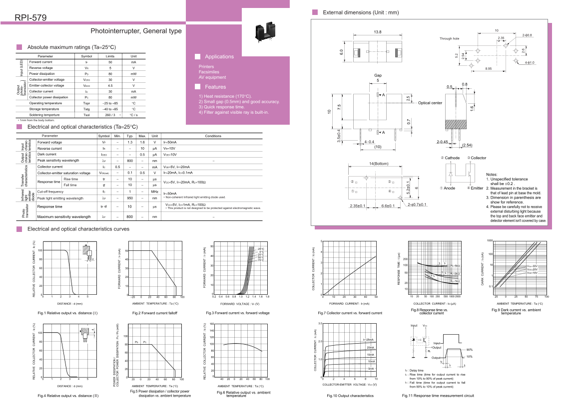
A reliable infrared photointerrupter designed for accurate light detection in industrial and automation applications. This detailed manual provides engineers with comprehensive technical specifications, including absolute maximum electrical ratings, measured response times, and performance curves plotted against varying ambient temperatures and distances. It covers all necessary metrics—such as forward voltage, relative output strength, and power dissipation—ensuring precise circuit design for automated controls, safety equipment, and industrial monitoring systems operable between -25°C and +85°C.
Page 1 Text Content
External dimensions (Unit : mm) RPI-579 ut pu
ph ot o- In pu t ( LE
ho to In fr ar ed ra ns fe ut pu In pu
tr an si st or
tr an si st or lig ht ch ar ac te ris tic ch ar ac ch ar ac
em itt er te ris tic te ris tic
Photointerrupter, General type di od 13.8
LA IV LL Ic LA IV LL Ic
Through hole 2.35
Absolute maximum ratings (Ta=25°C)
Parameter Symbol Limits Unit Applications
Forward current IF m A 4-φ1.0
Reverse voltage Printers
VR 8.95
Facsimiles
Power dissipation PD m W
AV equipment
Collector-emitter voltage VCEO
Emitter-collector voltage 0.8
VECO 4.5
Features 0.5
Collector current IC m A
Collector power dissipation PC m W 1) Heat resistance (170°C). 2) Small gap (0.5mm) and good accuracy.
Operating temperature Topr −25 to +85 °C Optical center
3) Quick response time.
Storage temperature Tstg −40 to +85 °C
4) Filter against visible ray is built-in.
Soldering temperture IS IP IO
Tsol 260 / 3 °C / s LL IS IP IO (m
∗ 1mm from the body bottom.
Electrical and optical characteristics (Ta=25°C) Parameter Symbol Min. Typ. Max. Unit Conditions
Forward voltage VF 1.3 1.6 IF=50m A 4−0.4 2-0.45
Reverse current IR µA VR=10V
Dark current ICEO 0.5 µA VCE=10V
Cathode Collector
Peak sensitivity wavelength λP nm
14(Bottom)
Collector current IC 0.5 m A VCE=5V, IF=20m A
Collector-emitter saturation voltage VCE(sat) 0.1 0.5 IF=20m A, IC=0.1m A
Notes:
Rise time tr µs 1. Unspecified tolerance
Response time VCC=5V, IF=20m A, RL=100Ω
shall be ±0.2 .
Fall time tf µs
Anode Emitter 2. Measurement in the bracket is
Cut-off frequency f C MHz
IF=50m A that of lead pin at base the mold.
∗ Non-coherent Infrared light emitting diode used.Peak light emitting wavelength 3. Dimension in parenthesis are λP nm
show for reference.
LA IV LL Ic IF VCC=5V, IC=1m A, RL=100Ωtr tf Response time 2-φ0.7±0.1
µs 2.35±0.1 6.6±0.1 4. Please be carefully not to receive
∗ This product is not designed to be protected against electromagnetic wave.
external disturbing light because λP nm −Maximum sensitivity wavelength the top and back face emitter and detector element isn't covered by case.
Electrical and optical characteristics curves
tr tf
RL=5kΩ VCE=30V
VCE=20V
tr tf VCE=10V RL=2kΩ
tf tr
RL=1kΩ
DISTANCE : d (mm) AMBIENT TEMPERATURE : Ta (°C) FORWARD VOLTAGE : VF (V) FORWARD CURRENT : IF (m A) COLLECTOR CURRENT : Ic (µA) AMBIENT TEMPERATURE : Ta (°C)
Fig.8 Response time vs. Fig.9 Dark current vs. ambient
Fig.1 Relative output vs. distance ( ) LL Fig.2 Forward current falloff Ic Fig.3 Forward current vs. forward voltage Fig.7 Collector current vs. forward current collector current temperature
LL IC
VCCInput
IF=25m A PCPD 2.0 6.
Input
20m A Output
90%RL
Output
10m A td
tr tf
td : Delay time r : Rise time (time for output current to rise from 10% to 90% of peak current) f : Fall time (time for output current to fall
COLLECTOR-EMITTER VOLTAGE : VCE (V)
DISTANCE : d (mm) AMBIENT TEMPERATURE : Ta (°C) AMBIENT TEMPERATURE : Ta (°C) from 90% to 10% of peak current)
Fig.5 Power dissipation / collector power
Fig.6 Relative output vs. ambient
Fig.4 Relative output vs. distance ( ) dissipation vs. ambient temperature temperature Fig.10 Output characteristics Fig.11 Response time measurement circuit IM t ( µs
ID (n
Page Summary Contents For ROHM RPI-579 Data Sheet
Manual Details
| Brand | ROHM |
|---|---|
| Pages | 2 |
| File Size | 50.69 KB |
| Published | June 19, 2026 |
Enter the captcha to get the download link:

Frequently Asked Questions
What is the recommended industrial use case for this device?
It features high heat resistance (170°C), a small 0.5mm gap, and excellent accuracy.
What are the operational temperature limits?
The product's stable operating temperature range is from -25°C to +85°C.
Can this device be used in critical life-support machinery?
No; it is not designed for equipment that could directly endanger human life. Consult a representative for such uses.
What are the maximum electrical ratings I should know?
The absolute maximum limits include 50 mA for forward current (IF) and 5 V for reverse voltage (VR).