ROHM RPI-392 Data Sheet
Summary
This versatile general-type photointerrupter is a high-reliability opto-sensor designed for varied detection applications. The comprehensive manual covers all necessary technical details, including absolute maximum ratings, operational limits, and detailed electrical/optical performance curves for temperature or distance variations. It is engineered for engineers designing sophisticated systems such as AV equipment, office automation gear, communication devices, and general electrical appliances requiring accurate optical sensing functionality.
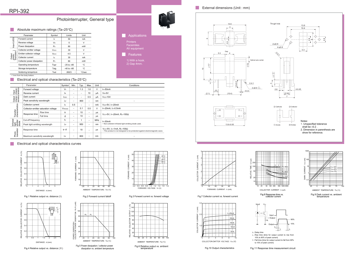
Page 1 Text Content
External dimensions (Unit : mm) RPI-392 ut pu
In fr ar ed ph ot o- In pu t ( LE
ut pu In pu
ho to lig ht ra ns fe tr an si st or
ch ar ac ch ar ac
tr an si st or em itt er ch ar ac te ris tic
te ris tic te ris tic
Photointerrupter, General type di od
LA IV LL Ic LA IV LL Ic
14.6 Thrugh hole
Absolute maximum ratings (Ta=25°C)
Parameter Symbol Limits Unit Applications
Forward current IF m A
Reverse voltage Printers
Facsimiles
Power dissipation PD m W
AV equipment
Collector-emitter voltage VCEO 3.3
Gap Emitter-collector voltage 45.3
VECO 4.5
Features
Collector current IC m A
Optical axis center
Collector power dissipation PC m W 1) With a hook. 2) Gap 4mm.
Operating temperature Topr −25 to +85 °C
Storage temperature Tstg −40 to +85 °C
Soldering temperture Tsol 260/3 °C/sec IS IP IO
∗ 1mm from the body bottom. LL IS IP IO / P (m IF
Electrical and optical characteristics (Ta=25°C)
Parameter Symbol Min. Typ. Max. Unit Conditions
Forward voltage VF 1.3 1.6 IF=50m A 0.8 4-0.45
Reverse current IR µA VR=5V (2.1) (10.4) (2.54)
Dark current ICEO 0.5 µA VCE=10V Peak sensitivity wavelength λP nm Collector current IC 0.5 m A VCE=5V, IF=20m A
Cathode Collector
Collector-emitter saturation voltage VCE(sat) 0.1 0.5 IF=20m A, IC=0.5m A
Rise time tr µs
Response time VCC=5V, IF=20m A, RL=100Ω
Fall time tf µs
Cut-off frequency f C MHz
IF=50m A Notes:
∗ Non-coherent Infrared light emitting diode used.Peak light emitting wavelength 1. Unspecified tolerance λP nm 13.6±0.05 Anode Emitter
shall be ±0.2 .
IF VCC=5V, IC=1m A, RL=100Ωtr tf Response time
LA IV LL IC µs 2. Dimension in parenthesis are
∗ This product is not designed to be protected against electromagnetic wave.
show for reference.
λP nm −Maximum sensitivity wavelength
Electrical and optical characteristics curves
tr tf
RL=5kΩ VCE=30V
VCE=20V
tr tf VCE=10V RL=2kΩ
tf tr
RL=1kΩ
−20 0.40.2 0.6 0.8 1.0 1.2 1.4 1.6 1.8 FORWARD VOLTAGE : VF (V)
AMBIENT TEMPERATURE : Ta (°C) FORWARD CURRENT : IF (m A) COLLECTOR CURRENT : IC (µA)
DISTANCE : d (mm) AMBIENT TEMPERATURE : Ta (°C)
Fig.8 Response time vs. Fig.9 Dark current vs. ambient
Fig.1 Relative output vs. distance ( ) Fig.2 Forward current falloff Fig.3 Forward current vs. forward voltage Fig.7 Collector current vs. forward current collector current temperature
LL IC LL IC (m
VCCInput
IF=25m A
0.8 PCPD 2.0
Input 20m A Output
0.6 90%RL
Output 10%
0. 10m A td
tr tf
td : Delay time Rise time (time for output current to rise from
0.5 1.5 2.5 10% to 90% of peak current) Fall time (time for output current to fall from 90%
AMBIENT TEMPERATURE : Ta (°C) COLLECTOR-EMITTER VOLTAGE : VCE (V)
DISTANCE : d (mm) AMBIENT TEMPERATURE : Ta (°C)
to 10% of peak current)
Fig.5 Power dissipation / collector power Fig.6 Relative output vs. ambient
(1 .5 Fig.10 Output characteristics
Fig.4 Relative output vs. distance ( ) dissipation vs. ambient temperature temperature Fig.11 Response time measurement circuit
LA IV IM tr, tf (µ s)
IC n A
Page Summary Contents For ROHM RPI-392 Data Sheet
Manual Details
| Brand | ROHM |
|---|---|
| Pages | 2 |
| File Size | 48.31 KB |
| Published | June 18, 2026 |
Enter the captcha to get the download link:
