RICOH RP505K SERIES Data Sheet
Summary
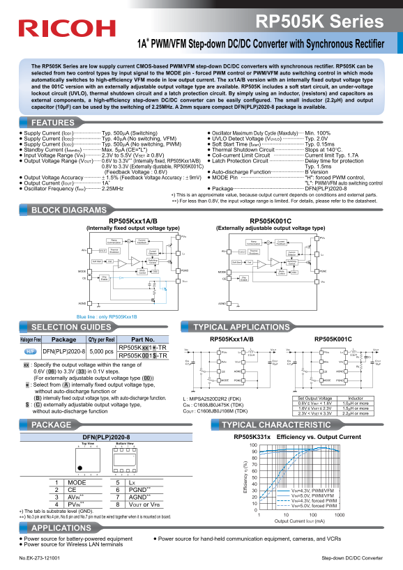
The RP505K Series offers a low-supply current, high-efficiency PWM/VFM step-down DC/DC converter ideal for portable electronics. Featuring automatic mode switching and synchronous rectification, it maximizes power efficiency while maintaining robust protection features like UVLO. This manual provides comprehensive specifications, selection guides (fixed or adjustable output voltage), and detailed application data necessary for hardware designers creating battery-powered equipment such as communication devices, cameras, and WLAN terminals.
Page 1 Text Content
RP505K Series
1A∗ PWM/VFM Step-down DC/DC Converter with Synchronous Rectifier
The RP505K Series are low supply current CMOS-based PWM/VFM step-down DC/DC converters with synchronous rectifier. RP505K can be selected from two control types by input signal to the MODE pin - forced PWM control or PWM/VFM auto switching control in which mode automatically switches to high-efficiency VFM mode in low output current. The xx1A/B version with an internally fixed output voltage type and the 001C version with an externally adjustable output voltage type are available. RP505K includes a soft start circuit, an under-voltage lockout circuit (UVLO), thermal shutdown circuit and a latch protection circuit. By simply using an inductor, (resistors) and capacitors as external components, a high-efficiency step-down DC/DC converter can be easily configured. The small inductor (2.2μH) and output capacitor (10μF) can be used by the switching of 2.25MHz. A 2mm square compact DFN(PLP)2020-8 package is available.
FEATURES • Supply Current (IDD1)·················· Typ. 500μA (Switching) • Oscillator Maximum Duty Cycle (Maxduty)···· Min. 100% • Supply Current (IDD2)·················· Typ. 40μA (No switching, VFM) • UVLO Detect Voltage (VUVLO) ·············· Typ. 2.0V • Supply Current (IDD2)·················· Typ. 500μA (No switching, PWM) • Soft Start Time (tstart) ···························· Typ. 0.15ms • Standby Current (Istandby) ············ Max. 5μA (CE="L") • Thermal Shutdown Circuit ··················· Stops at 140°C. • Input Voltage Range (VIN) ·········· 2.3V to 5.5V (VSET ≥ 0.8V) • Coil-current Limit Circuit ···················· Current limit Typ. 1.7A • Output Voltage Range (VOUT)····· 0.6V to 3.3V∗∗ (Internally fixed, RP505Kxx1A/B) • Latch Protection Circuit ······················· Delay time for protection
0.8V to 3.3V (Externally djustable, RP505K001C) Typ. 1.5ms (Feedback Voltage : 0.6V) • Auto-discharge Function······················ B Version
• Output Voltage Accuracy ··········· ± 1.5% (Feedback Voltage Accuracy : ± 9m V) • MODE Pin ·········································· "H": forced PWM control, • Output Current (IOUT)·················· 1A∗ "L": PWM/VFM auto switching control • Oscillator Frequency (fosc)·········· 2.25MHz • Package··············································· DFN(PLP)2020-8
∗) This is an approximate value, because output current depends on conditions and external parts. ∗∗) For less than 0.8V, the input voltage range is limited. For details, please refer to the datasheet.
BLOCK DIAGRAMS RP505Kxx1A/B RP505K001C (Internally fixed output voltage type) (Externally adjustable output voltage type)
PVIN PVIN
Ramp Current Ramp Current Compensation Feedback Compensation Feedback
ffi ci en cy
AVIN UVLO Thermal Thermal
Shutdown Current AVIN UVLO Current
Detector LX Shutdown
Detector LX
Soft Start Vref Switching Switching
Control Soft Start Vref Control
Mode OSC PGNDMODE Mode PGNDMODE
Control Control OSC
Chip Chip
CE Enable CE
Enable
VOUT VFB
AGND AGND
SELECTION GUIDES TYPICAL APPLICATIONS
Halogen Free Package Q'ty per Reel Part No. RP505Kxx1A/B RP505K001C
RP505K.xx.1.∗ -TR VIN VOUT VIN VOUT
DFN(PLP)2020-8 5,000 pcs PVIN LX PVIN LX
RP505K.00.1.$.-TR R1 C1
CIN AVIN VOUT COUT CIN AVIN VFB COUT 4.7μF 10μF 4.7μF 10μF
.xx. : Specify the output voltage within the range of R2
0.6V (.06.) to 3.3V (.33.) in 0.1V steps. CE AGND CE AGND
(For externally adjustable output voltage type (.00.))
MODE PGND MODE PGND
.∗ : Select from (.A.) internally fixed output voltage type, without auto-discharge function or
(.B.) internally fixed output voltage type, with auto-discharge function. L : MIPSA2520D2R2 (FDK) Set Output Voltage Inductor 0.6V ≤ VSET < 1.6V 1.0μH or more
.$. : (.C.) externally adjustable output voltage type, CIN : C1608JB0J475K (TDK)
1.6V ≤ VSET ≤ 2.3V 1.5μH or more
without auto-discharge function COUT : C1608JB0J106M (TDK)
2.3V < VSET ≤ 3.3V 2.2μH or more
PACKAGE TYPICAL CHARACTERISTIC
DFN(PLP)2020-8 RP505K331x Efficiency vs. Output Current
Bottom View Top View
1 MODE LX 2 CE PGND∗∗ VIN=4.3V, PWM/VFM
∗∗ VIN=5.0V, PWM/VFM
3 AVIN AGND∗∗
VIN=4.3V, forced PWM
4 PVIN VOUT or VFB VIN=5.0V, forced PWM
∗) The tab is substrate level (GND). ∗∗) No.3 pin and No.4 pin, No.6 pin and No.7 pin must be wired together when it is mounted on board.
Output Current IOUT (m A)
APPLICATIONS • Power source for battery-powered equipment • Power source for hand-held communication equipment, cameras, and VCRs • Power source for Wireless LAN terminals No.EK-273-121001 Step-down DC/DC Converter
Page Summary Contents For RICOH RP505K SERIES Data Sheet
Manual Details
| Brand | Ricoh |
|---|---|
| Pages | 2 |
| File Size | 346.57 KB |
| Published | June 01, 2026 |
Enter the captcha to get the download link:

Frequently Asked Questions
How can I switch between PWM forced control and VFM auto switching?
Use the MODE pin: set it to 'H' for forced PWM or 'L' for automatic PWM/VFM control.
What external components must I use with the RP505K converter?
You simply need an inductor, resistors, and capacitors to configure a high-efficiency step-down DC/DC converter.
Are there safety features built into this DC/DC converter?
Yes, it includes UVLO, soft start, thermal shutdown (at 140°C), latch protection, and coil-current limit circuits.
Does the circuit adapt for high efficiency at low output current?
Yes; if set to auto-switching mode, it automatically switches to the highly efficient VFM mode when output current is low.