# A B C D E F G H I J K L M N O P Q R S T U V W X Y Z

Ricoh R5460x Series Data Sheet User Guide

Summary

This high voltage comparator IC series provides essential overcharge/overdischarge, current monitoring, and short circuit protection for rechargeable two-cell Lithium-ion and Lithium polymer batteries. Designed for demanding battery management systems, it features multiple detection thresholds and configurable release mechanisms to ensure optimal safety and longevity. The manual details various versions and technical specifications necessary for integrating precise, reliable protection into advanced power solutions.
📄 Preview PAGE OF 31

Page 1 Text Content

R5460x SERIES

Li-ION/POLYMER 2-CELL PROTECTOR

NO.EA-165-091221

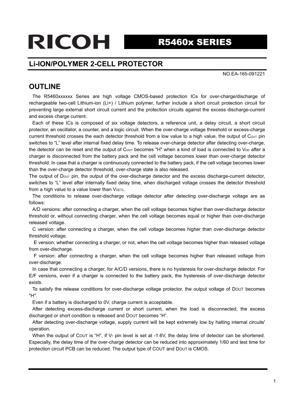
OUTLINE The R5460xxxxxx Series are high voltage CMOS-based protection ICs for over-charge/discharge of rechargeable two-cell Lithium-ion (Li+) / Lithium polymer, further include a short circuit protection circuit for preventing large external short circuit current and the protection circuits against the excess discharge-current and excess charge current. Each of these ICs is composed of six voltage detectors, a reference unit, a delay circuit, a short circuit protector, an oscillator, a counter, and a logic circuit. When the over-charge voltage threshold or excess-charge current threshold crosses the each detector threshold from a low value to a high value, the output of COUT pin switches to “L” level after internal fixed delay time. To release over-charge detector after detecting over-charge, the detector can be reset and the output of COUT becomes "H" when a kind of load is connected to VDD after a charger is disconnected from the battery pack and the cell voltage becomes lower than over-charge detector threshold. In case that a charger is continuously connected to the battery pack, if the cell voltage becomes lower than the over-charge detector threshold, over-charge state is also released. The output of DOUT pin, the output of the over-discharge detector and the excess discharge-current detector, switches to “L” level after internally fixed delay time, when discharged voltage crosses the detector threshold from a high value to a value lower than VDET2. The conditions to release over-discharge voltage detector after detecting over-discharge voltage are as follows: A/D versions: after connecting a charger, when the cell voltage becomes higher than over-discharge detector threshold or, without connecting charger, when the cell voltage becomes equal or higher than over-discharge released voltage. C version: after connecting a charger, when the cell voltage becomes higher than over-discharge detector threshold voltage. E version: whether connecting a charger, or not, when the cell voltage becomes higher than released voltage from over-discharge. F version: after connecting a charger, when the cell voltage becomes higher than released voltage from over-discharge. In case that connecting a charger, for A/C/D versions, there is no hysteresis for over-discharge detector. For E/F versions, even if a charger is connected to the battery pack, the hysteresis of over-discharge detector exists. To satisfy the release conditions for over-discharge voltage protector, the output voltage of DOUT becomes "H". Even if a battery is discharged to 0V, charge current is acceptable. After detecting excess-discharge current or short current, when the load is disconnected, the excess discharged or short condition is released and DOUT becomes “H”. After detecting over-discharge voltage, supply current will be kept extremely low by halting internal circuits' operation. When the output of COUT is “H”, if V- pin level is set at -1.6V, the delay time of detector can be shortened. Especially, the delay time of the over-charge detector can be reduced into approximately 1/60 and test time for protection circuit PCB can be reduced. The output type of COUT and DOUT is CMOS.

Page Summary Contents For Ricoh R5460x Series Data Sheet User Guide

Page 1 R5460x SERIES Li-ION/POLYMER 2-CELL PROTECTOR NO.EA-165-091221 OUTLINE The R5460xxxxxx Series are high voltage CMOS-based protection ICs for over-charge/discharge of rechargeable two-cell Lithium-ion ...
Page 2 FEATURES Manufactured with High Voltage Tolerant Process ................ Absolute Maximum Rating 30V Low supply current ........................................Supply current (At normal mode) Typ. 4....
Page 3 BLOCK DIAGRAMS A/ D/ E/ F version DS Circuit Oscillator Counter Level Logic Shift Circuit Short Delay Detector VD1L Logic Circuit DOUT COUT V- VSS C version DS Circuit Oscillator Counter Level Logic S...
Page 4 SELECTION GUIDE In the R5460xxxxxx Series, input threshold of over-charge, over-discharge, excess discharge current, and the package and taping can be designated. Part Number is designated as follows:...
Page 5 PIN DESCRIPTIONS Pin No. Symbol Description SOT23-6 PLP1820-6 1 3 DOUT Output pin of over-discharge detection, CMOS output 2 1 COUT Output pin of over-charge detection, CMOS output 3 2 V- Pin for char...
Page 6 ELECTRICAL CHARACTERISTICS R5460x2xx AA/AD/AE version Unless otherwise specified, Topt=25°C Symbol Item Conditions Min. Typ. Max. Unit Note1 VDD1 Operating input voltage Voltage defined as VDD-Vss 1.5...
Page 7 R5460x2xx AC version Unless otherwise specified, Topt=25°C Symbol Item Conditions Min. Typ. Max. Unit Note1 VDD1 Operating input voltage Voltage defined as VDD-Vss 1.5 10.0 V A Voltage defined as VDD-...
Page 8 R5460x2xx AF version Unless otherwise specified, Topt=25°C Symbol Item Conditions Min. Typ. Max. Unit Note1 VDD1 Operating input voltage Voltage defined as VDD-Vss 1.5 10.0 V A Voltage defined as VDD-...
Page 9 OPERATION VDET1U,VDET1L / Over-Charge Detectors The VDET1U and VDET1L monitor the voltage between VDD pin and VC pin (the voltage of Cell1) and the voltage between VC pin and VSS pin (the voltage of C...
Page 10 detector exists. When a cell voltage equals to zero, if the voltage of a charger is equal or more than 0V-charge minimum voltage (Vst), COUT pin becomes "H" and a system is allowable to char...
Page 11 DS (Delay Shorten) function Output delay time of over-charge, over-discharge, and release from those detecting modes can be shorter than those setting value by forcing equal or less than the delay sho...
Page 12 TIMING CHART 1) Timing diagram of Over-charge,Excess charge current AA/AC/AD version Excess Charger Open Connect Charger Connect Load Charge and Connect Current Load V DD V C - V DET1 V REL1 V C V SS-...
Page 13 AE/AF version Excess Disconnect Connect Charger Connect Load Charge Charger Current + Connect Load V DET1U V DD V - REL1U C V DET1L V C V SS - V REL1L V- V SS t REL1 t VREL1 t V REL4 t VDET4 C OUT DET...
Page 14 2) Over-discharge, Excess discharge current, Short circuit AA/AD version Excess discharge current Short Connect Load Connect Charger Open Open V REL2U V DD V C - V DET2U V REL2L V C V SS V DET2L V DD ...
Page 15 AC version Connect Ov er-discharge Connect Connect Load Connect Charger Open Short Open Charger Current DD V C - V DET2U V SS C - V V DET2L DD short V DET3 SS DET4 t REL2 V V V V REL2 DET3 t REL3t t R...
Page 16 AE version Connect Ov er Discharge Current Short Connect Load Charger Open Open V DD V C - V REL2U V DET2U V C V SS - VREL2L V DET2L VDD Vshort VDET3 V- V SS VDET4 t V REL2 t VREL2 t VREL3 t V REL3 D ...
Page 17 3) Operation with unbalanced cells AC version Connect Load Connect Charger Connect Load Connect Charger Open VDET1L VREL1L VDD - VC VC - VSS VDET2L V- VDET3 VSS VDET4 COUT t VDET1 t VREL1 DOUT t VDET2...
Page 18 TYPICAL APPLICATION AND TECHNICAL NOTES VDD C1 0.1μF Vc R5460 COUT DOUT Vss TECHNICAL NOTES R1, R2, C1 and C2 stabilize a supply voltage to the R5460xxxxxx. A recommended R1, R2 value is less than 1kΩ...
Page 19 TEST CIRCUITS V V- DOUT V COUT OSCILLOSCOPE VDD VDD VC VC COUT DOUT VDD VDD VC VC COUT V COUT VDD VDD VC VC DOUT COUT VSS VSS
Page 20 VDD COUT VDD DOUT
Page 21 TYPICAL CHARACTERISTICS (Part 1) 1) Minimum Operating Voltage for 0V Cell Charging 2) Over-charge voltage threshold (Cell1) vs. Temperature R5460x201AC R5460x201AC VDD=VSS=0V Vc-Vss=3.5V ve r- ch ar g...
Page 22 el ea se ol ta ge fr om ve r- ut pu t D el ay im of el ea se ch ar ge el l2 L1 L( fro ve r-c ha rg t V L1 (m s) 5) Release Voltage from Over-charge (Cell2) vs. 6) Output Delay of Over-charge Detector ...
Page 23 ut pu t D el ay im fo r E xc es ut pu t D el ay im fo el ea se fr om ve r- di sc ha rg di sc ha rg e- cu rr en t D et ec to r t ET el ea se fr om ve r- di sc ha rg R5460x EL L2 (V 11) Release Voltage ...
Page 24 ut pu t D el ay fo r d et ec tin Sh or t D et ec to r T hr es ho ld xc es ch ar ge ur re nt el ea se es is ta nc fr om xc es s- T( V) t V ET 4( s) di sc ha rg cu rr en t R SH T( kΩ 17) Short Detector ...
Page 25 Pc ol ta ge f C el ay hr te ni ng od Th re sh ol ch ol ta ge f D 23) Delay Shortening Mode Voltage vs. Temperature 24) Nch ON Voltage of COUT vs. Temperature R5460x201AC R5460x201AC -0.4 VDD-VC=VC-VSS...
Page 26 ut pu t d el ay f o ve r- ta nd by ur re nt Is tb (u di sc ha rg t V T2 [m s] ut pu t d el ay f o ve r- ch ar ge t V ET s] 29) Standby Current vs. Temperature (Ver. A.) 30) Standby Current vs. Tempera...
Page 27 ut pu t d el ay f s ho rt ut pu t d el ay f e xc es ut pu t d el ay f e xc es ch ar ge -c ur re nt t V ET s] R5460x pr ot ec tio t S μs di sc ha rg cu rre nt 5) Output Delay for Excess Discharge Curre...
Page 28 Su pp ly ur re nt ID (u A) Part 3 Supply Current dependence on VDD Test Circuit PACK+ CELL1 VDD C1 0.1μF Vc R5460 COUTDOUTVss Su pp ly ur re nt ID (u A) CELL2 PACK- Supply Current vs. VDD A version C ...
Page 29 VD T2 [V ET [V Part 4 Over-charge detector, Release voltage from Over-charge, Over-discharge detector, Release voltage from Over-discharge dependence on External Resistance value Test Circuit PACK+ CE...
Page 30 ha rg er ol ta ge f R el ea se fr om ve r- di sc ha rg e[ V] Part 5 Charger Voltage at Released from Over-discharge with a Charger dependence on R2 Test Circuit PACK+ CELL1 VDD C1 COUTDOUT Vss CELL2 P...
Page 31 R5460x CODE LIST Part No. VDET1(V) VREL1(V) VDET2(V) VREL2(V) VDET3(V) VDET4(V) t VDET1(s) t VDET2(ms) t VDET3(ms) t VDET4(ms) t SHORT(us) 0V Charge R5460N201AC 4.350 4.150 2.300 0.200 -0.400 OK R5460...

Manual Details

Brand Ricoh
Pages 31
File Size 637.71 KB
Published June 02, 2026
70 views

Enter the captcha to get the download link:

captcha

Frequently Asked Questions

What types of battery failure does the R5460x series protect against?

It protects against over-charge, over-discharge, large external short circuit current, and both excess charge and excess discharge currents.

How do I release an over-charge state after it is detected?

The detector must be reset by connecting a load to VDD after the charger is disconnected until the cell voltage drops below the over-charge threshold.

What determines the reset condition for detecting over-discharge voltage?

This depends on the version: 'D' versions require connection of a charger or achieving voltage equal to/higher than the released voltage. 'E' and 'F' always check against the released voltage.

What is the standby current draw maximum across different versions?

For A/D/E versions, the standby current is typically 1.2μA (Max.). For C/F versions, it can be as low as 0.1μA (Max.).