Panasonic MA2SV03 Data Sheet/Manual
Summary
These Variable Capacitance Diodes are precision components designed for high-frequency radio frequency (RF) circuits, enabling capacitance tuning and signal management in compact applications. Featuring a superior C-V linearity and small series resistance, the model utilizes an SS-Mini type package for effortless integration into modern electronics. This technical manual provides comprehensive data sheets covering absolute maximum ratings, detailed electrical curves—including I-V, C-V dependence, and temperature performance—making it essential for RF engineers designing frequency oscillators (VCOs) or sensitive impedance matching networks.
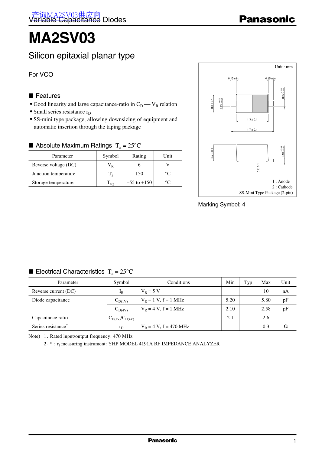
Page 1 Text Content
查询MA2SV03供应商 Variable Capacitance Diodes
MA2SV03 Silicon epitaxial planar type
Unit : mm
For VCO
0.15 min. 0.15 min.
Features Good linearity and large capacitance-ratio in CD VR relation Small series resistance r D
SS-mini type package, allowing downsizing of equipment and 1.3 ± 0.1
automatic insertion through the taping package
Absolute Maximum Ratings Ta = 25°C Parameter Symbol Rating Unit Reverse voltage (DC) VR Junction temperature Tj °C
1 : Anode
Storage temperature Tstg −55 to +150 °C
2 : Cathode
SS-Mini Type Package (2-pin)
Marking Symbol: 4
to .1
Electrical Characteristics Ta = 25°C
Parameter Symbol Conditions Min Typ Max Unit 0. 0.
Reverse current (DC) IR VR = 5 V n A Diode capacitance CD(1V) VR = 1 V, f = 1 MHz 5.20 5.80 p F
CD(4V) VR = 4 V, f = 1 MHz 2.10 2.58 p F
Capacitance ratio CD(1V)/CD(4V) 2.1 2.6 Series resistance* r D VR = 4 V, f = 470 MHz 0.3 Note) 1.Rated input/output frequency: 470 MHz 2.* rf measuring instrument: YHP MODEL 4191A RF IMPEDANCE ANALYZER
Page Summary Contents For Panasonic MA2SV03 Data Sheet/Manual
Manual Details
| Brand | Panasonic |
|---|---|
| Pages | 2 |
| File Size | 38.42 KB |
| Published | July 16, 2026 |
Enter the captcha to get the download link:

Frequently Asked Questions
What is the junction temperature limit for this diode?
The absolute maximum junction temperature ($T_j$) rating is $150 ext{ °C}$.
How should I power down or store the device?
The anode storage temperature ($ ext{stg} 2$) ranges from $-55$ to $+150 ext{ °C}$ in the SS-mini type package.
What is the typical capacitance ratio for this component?
The typical capacitance ratio ($C/C$) ranges from $2.1$ to $2.6$.
What are the minimum and maximum values for the reverse current?
At a standard test condition of Reverse voltage ($ ext{DC}$) $ ext{V} = 5 ext{ V}$, the reverse current is between $10 ext{ nA}$.