# A B C D E F G H I J K L M N O P Q R S T U V W X Y Z

Panasonic AN8031 Data Sheet / Manual

Summary

The AN8031 is a miniature, monolithic active filter control IC designed to combat harmful harmonic distortion in commercial power supplies and AC lines. By integrating multiple advanced protection functions—such as overvoltage and low voltage monitoring—into one package, it simplifies the construction of sophisticated active filters. This regulator is ideally suited for demanding applications like modern lighting equipment and various switching power supply units requiring stable, high-quality electrical performance. The comprehensive manual provides detailed technical specifications, operational ratings, and application examples needed for precise engineering integration.
📄 Preview PAGE OF 21

Page 1 Text Content

查询AN8031供应商 Voltage Regulators

AN8031 Active filter control IC Overview Unit: mm

In supplying electric power from commercial power 6.0±0.3 3.3±0.25

supply to various electrical equipment, there is a possi- bility that the harmonic distortion generated in the power line may give obstruction to the power facilities or other electrical equipment. The use of active filter is one of the methods to solve the harmonic distortion problems. The AN8031 is a monolithic IC which incorporates the control and protection functions into one package so that the active filter can be constructed easily. It is most suitable for the measures against the harmonic distortion problems such as lighting equipment.

Features

Self-excited peak current mode is adapted.

Built-in protection circuit for preventing the overvolt- SIP009-P-0000C

age generated under a small load

Easy constant setting with enlarged dynamic range of multiplier and error amplifier. Using totem pole output circuit which allows the power MOSFET to be directly driven. Built-in low voltage protection circuit which ensures the on-resistance during the power MOSFET operation. Timer circuit is built in for realizing automatic start.

Applications

Lighting equipment and switching power supply equipment

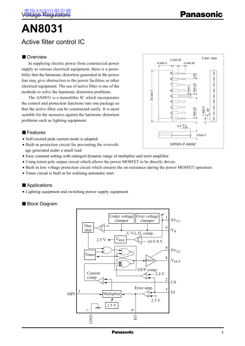
Block Diagram

Under voltage Over voltage

clamper clamper SVCC

One shot VB

U.V.L.O. comp. 2.5 V VREF

Timer

Drive VOUT

OVP comp.

2.6 VCurrent

comp.

Error amp.

MPI Multiplier

Page Summary Contents For Panasonic AN8031 Data Sheet / Manual

Page 1 查询AN8031供应商 Voltage Regulators AN8031 Active filter control IC Overview Unit: mm In supplying electric power from commercial power 6.0±0.3 3.3±0.25 supply to various electrical equipment, there is a p...
Page 2 AN8031 Voltage Regulators Pin Descriptions Pin No. Symbol Description SVCC Control system supply-voltage pin CS Comparator input pin MPI Multiplier input pin EO Error amplifier output pin / multiplier...
Page 3 Voltage Regulators AN8031 Electrical Characteristics (continued) at Ta = 25°C Parameter Symbol Conditions Min Typ Max Unit Multiplier input D-range (upper limit) VMPIH VEO = 5 V 4.0 4.5 Multiplier out...
Page 4 AN8031 Voltage Regulators Terminal Equivalent Circuits Pin No. Equivalent circuit Description I/O SVCC: The supply voltage terminal for control system. It monitors the supply voltage and has operating...
Page 5 Voltage Regulators AN8031 Terminal Equivalent Circuits (continued) Pin No. Equivalent circuit Description I/O Approx. 7.1 VPVCC Approx. 7.1 V The terminal is connected via the transformer's Upper limi...
Page 6 AN8031 Voltage Regulators Application Notes [1] PD  Ta curve of SIP009-P-0000C PD  Ta Independent IC without a heat sink Rth( j−a) = 143°C/W PD = 874 m W (25°C) Po er is si pa tio Ambient temperatur...
Page 7 Voltage Regulators AN8031 Application Notes (continued) [2] Operation descriptions (continued) 1. Normal control (continued) 2) Control outline description (Refer to figure 2 and figure 3.) (1) Input ...
Page 8 AN8031 Voltage Regulators Application Notes (continued) [2] Operation descriptions (continued) 1. Normal control (continued) 2) Control outline description (Refer to figure 2 and figure 3.) (continued...
Page 9 Voltage Regulators AN8031 Application Notes (continued) [2] Operation descriptions (continued) 1. Normal control (continued) 2) Control outline description (Refer to figure 2 and figure 3.) (continued...
Page 10 AN8031 Voltage Regulators Application Notes (continued) [2] Operation descriptions (continued) 1. Normal control (continued) 3) Description of each function (continued) (1) VB (continued) VB lower lim...
Page 11 Voltage Regulators AN8031 Application Notes (continued) [2] Operation descriptions (continued) Delay capacitor 1. Normal control (continued) AN8031 3) Description of each function (continued) (1) VB (...
Page 12 AN8031 Voltage Regulators Application Notes (continued) [2] Operation descriptions (continued) 1. Normal control (continued) 3) Description of each function (continued) ot em ol ty pe (4) EI/EO ou tp ...
Page 13 Voltage Regulators AN8031 Application Notes (continued) [2] Operation descriptions (continued) 1. Normal control (continued) 3) Description of each function (continued) (6) VCC ICC IC operation U.V.L....
Page 14 AN8031 Voltage Regulators Application Notes (continued) [2] Operation descriptions (continued) 2. Protection circuit 1) Timer In control of this IC, the chopper circuit does not start unless the first...
Page 15 Voltage Regulators AN8031 Application Notes (continued) [2] Operation descriptions (continued) 2. Protection circuit (continued) 2) Overvoltage protection (1) Cause of overvoltage In the booster chopp...
Page 16 AN8031 Voltage Regulators Application Notes (continued) [2] Operation descriptions (continued) 2. Protection circuit (continued) 2) Overvoltage protection (continued) (2) Description of overvoltage pr...
Page 17 Voltage Regulators AN8031 Application Notes (continued) [2] Operation descriptions (continued) 2. Protection circuit (continued) 2) Overvoltage protection (continued) (3) Output voltage overshoot at s...
Page 18 AN8031 Voltage Regulators Application Notes (continued) [3] Difference between the AN8031 and the AN 8032 AN8031 → EI terminal is used in common for both the output voltage monitor function and the ov...
Page 19 Voltage Regulators AN8031 Application Circuit Example Application circuit µF SB PI GND7 0. µFR
Page 20 AN8031 Voltage Regulators Application Circuit Example (continued) Normal operation waveforms Horizontal axis 1 ms/div 10 ms/div /d iv 0. /d iv 0. /d iv /d iv /d iv 0. /d iv /d iv Measuring point (EIN)...
Page 21 Voltage Regulators AN8031 Application Circuit Example (continued) Waveforms at start Horizontal axis 20 ms/div /d iv 0. /d iv /d iv 0. /d iv Measuring point (EOI) Waveforms at stop Horizontal axis 20 ...

Manual Details

Brand Panasonic
Pages 21
File Size 216.00 KB
Published June 21, 2026
13 views

Enter the captcha to get the download link:

captcha

Frequently Asked Questions

What is the primary function of using active filters?

Active filters are used to solve harmonic distortion problems in power lines, which can obstruct power facilities or electrical equipment.

What types of equipment does the AN8031 regulate?

It is suitable for lighting equipment and switching power supply equipment. For general applications, it performs voltage regulation.

How does the AN8031 IC assist in active filter construction?

It incorporates four control and protection functions into a single package, making active filter construction easy.

What ambient temperature range can the AN8031 operate within?

The recommended operating ambient temperature range is -30 to +85 °C.