Page 1
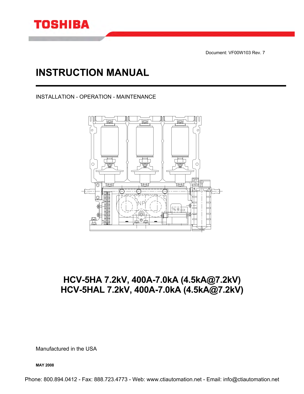
Document: VF00W103 Rev. 7 INSTRUCTION MANUAL INSTALLATION - OPERATION - MAINTENANCE HCV-5HA 7.2k V, 400A-7.0k A (4.5k [email protected] V) HCV-5HAL 7.2k V, 400A-7.0k A (4.5k [email protected] V) Manufactured in the USA MAY...
Page 2
MAY 2008 Phone: 800.894.0412 - Fax: 888.723.4773 - Web: www.ctiautomation.net - Email: [email protected]
Page 3
INTRODUCTION Page 2 READ THIS MANUAL carefully for important information about safety, handling, and maintenance, for general-purpose NEMA Class E magnetic controllers. This manual and all accompanyin...
Page 4
TABLE OF CONTENTS Page 3 Page Page SAFETY DATA 4 MAINTENANCE 17 Safety Data Information 4 General Inspection 17 Vacuum Interrupter 18 Bearing 19 GENERAL 6 Closing Coils 19 Latch Mechanism 19 Recommend...
Page 5
Page 4 SAFETY DATA QUALIFIED OPERATORS ONLY Only qualified persons are to install, operate, or service this equipment according to all applicable codes and established safety practices. A qualified pe...
Page 6
SAFETY DATA Page 5 IMPORTANT MESSAGES Read this manual and follow its instructions. Signal words such as DANGER, WARNING, CAUTION, and NOTE will be followed by important safety information that must b...
Page 7
Page 6 GENERAL Please read this manual and all accompanying documentation in its entirety prior to installation and operation. These instructions are not intended to cover all details, combinations or...
Page 8
KEEP THESE INSTRUCTIONS FOR FUTURE REFERENCE Phone: 800.894.0412 - Fax: 888.723.4773 - Web: www.ctiautomation.net - Email: [email protected]
Page 9
RECEIVING & HANDLING Page 7 RECEIVING Upon receipt of the equipment, make an immediate inspection for any damages which may have occurred during shipment. When the contactor is received it should ...
Page 10
Page 8 GENERAL DESCRIPTION SERVICE CONDITIONS Application Condition The type HCV vacuum contactor is manufactured in accordance with IEC 60470 (1974), NEMA ICS 3 Part 2 (1993). The vacuum contactor sh...
Page 11
GENERAL DESCRIPTION Page 9 CONTACTOR RATINGS HCV-5HA Rated Voltage 7200 Volts Rated Current 400 Amps Interrupting Capacity 7000A RMS Symmetrical @5000V Max. 4500A RMS Symmetrical @7200V Max. Permissib...
Page 12
Page 10 STRUCTURE Fig. 1 Construction of HCV-5HA & HCV-5HAL Phone: 800.894.0412 - Fax: 888.723.4773 - Web: www.ctiautomation.net - Email: [email protected]
Page 13
PRE-OPERATION SET-UP Page 11 APPLICATION PRECAUTIONS 1) Verify that the voltage and current applied is within the specified ratings. (See application table, page 5). 2) When the contactor is used with...
Page 14
Page 12 PRE-OPERATION SET-UP CONTROLS The drive unit for the closing coil assembly is installed in a cavity in the molded frame housing. The closing circuit can be operated by applying either AC or DC...
Page 15
PRE-OPERATION SET-UP Page 13 CONNECTION OF CONTROL POWER SUPPLY Figures 3 and 4 show the internal connections of the magnetically held (normally energized) type and the latched type respectively. Conn...
Page 16
ONTRO Page 14 LS Page 14 CONTROLS Contacts or Jumper Wire Fig. 5 Internal Configuration of Drive Unit. STANDARD OPERATION CIRCUIT The following figures illustrate the vacuum contactor and its auxiliar...
Page 17
LATCHED CIRCUIT Page 15 Fig. 7a Standard Operation Circuit Diagram of Latched Type Using Shunt Trip REMOTE OPERATION SWITCH 2EOFFOFF ON ON LOCAL REMOTE CR VCTT START INTERLOCK CONTROL RELAY Fig. 7b St...
Page 18
Page 16 TRIAL OPERATION TRIAL OPERATION MAKE SURE MAIN POWER IS OFF. After mounting and wiring of the vacuum contactor, make the following inspections. 1) Check for any loose connections. 2) Check for...
Page 19
MAINTENANCE Page 17 GENERAL INSPECTION MAINTENANCE AND INSPECTION LA TC LE TR IS TS TH IN IR IT IS TI IN TE The following maintenance and inspections are recommended to maintain the performance level ...
Page 20
Page 18 MAINTENANCE Make Sure Power Is Turned Off. MAINTENANCE Location Maintenance Procedure Vacuum Check the upper and lower flanges and interrupter shaft to see if they are Interrupter contaminated...
Page 21
MAINTENANCE Page 19 Location Maintenance Procedure Gap/Wipe Standard Values (contactor in new condition) Contactor Contact Gap Wipe (new) Allowable Wear Vacuum Normally Interrupter 4.0-4.2mm >2.3mm...
Page 22
Page 20 MAINTENANCE PROCEDURE FOR REPLACING VACUUM INTERRUPTERS When a vacuum interrupter has reached a specified life (250,000 operations) or when it is damaged, it is recommended that it be replaced...
Page 23
MAINTENANCE Page 21 MOUNTING 1) Remove the conductive nut from the vacuum interrupter being replaced and attach it to the new vacuum interrupter as shown in Fig. 10. 2) Put the conductive collar on th...
Page 24
Page 22 MAINTENANCE on ta ct or oe no t c lo se TROUBLESHOOTING on ta ct or oe no t o pe (L at ch ty pe Turn off main power before any inspections are conducted. Tr ip oi l o ve rh ea te d. Table 4 SO...
Page 25
OUTLINE Page 23 MOUNTING HOLE LAYOUT Fig. 12 Types HCV-5HA, HCV-5HAL Phone: 800.894.0412 - Fax: 888.723.4773 - Web: www.ctiautomation.net - Email: [email protected]
Page 26
Page 24 WARRANTY AND LIMITATION OF LIABILITY Toshiba International Corporation ("Company") warrants that all equipment and parts described herein will be free from defects in materials and w...