Page 1
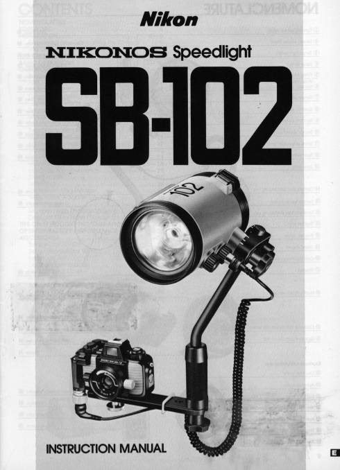
Nikon NIKONOS Speedlighf INSTRUCTION MANUAL
Page 2
NOMENCLATURE ______ _ CD Synchro socket index Joint collar @ Flash head positioning index @ Joint plate ® i ion mark @ i ion mark (@I (J) Sensor socket ® ro socket ® Synchro socket cover Joint @ @ Snp...
Page 3
CONTENTS ________ _ NOMENCLATURE . . . . . . . . . . . . . . . . . . . . . . . . . . . . . . 2 FOREWORD .. ..... 4 PREPARATION .......... ................... 4-6 Examining and lubricating the O-rings ...
Page 4
FOREWORD ________ _ The Nikonos 8peedlight 88-102, an amphibious high firing capability for wireless multiple flash photography, performance electronic flash unit with a sil icon-con and a target-li...
Page 5
PREPARATION-continued Examining and lubricating the O-rings: tions. If an O-ring is properly lubricated, it will glisten 1. To remove the O-rings, except those in the synchro and will not have "g...
Page 6
PREPARATION-continued ______ _ The preceding instructions must be performed on each user-serviceable O-ring prior to each dive day and, if possible, prior to each dive . By following these pro cedure...
Page 7
TIPS ON SPEEDLIGHT CARE 1. After using the speedlight and camera under removed in one of these situations, for instance, water, rinse them both as soon as possible in to exchange batteries, use a vin...
Page 8
BASIC OPERATI,;:::O..:....:N~S =======~===~=----==-= 1. Unlock the buckle 2 Remove the battery Unlock the silver buckle catches from the pins on the speedlight lock/release latches • chamber cap @ cas...
Page 9
5 Replace the C-type 6. Replace the battery 7, lock the buckles. • battery cartridge in chamber cap. • Push the battery chamber cap While holding the buckles away against the speedlight case so it is ...
Page 10
BASIC OPERATIONS-confinued ___ _ 11 Insert the joint plate 12 Lock the joint. 13. Loosen the joint • into the joint collar @ • Align the flash head position lever ing index @ with the "normal &q...
Page 11
18 Attach the bracket • The correct arm/bracket position is with the 17 Loosen the arm three washers on the underside of the • knob • ® to the arm. bracket, the rubber side of the bracket facing Turn ...
Page 12
BASIC OPERATIONS-confinued ___ _ 22 Connect the sync Check the a·ring: Before con 23 Remove the synchro necting the camera plug to the • cord @ to the • socket cover ®. camera, examine the plug 's O-...
Page 13
26. Set the ASA/ISO film In the photograph, the shooting 27 Set the shutter si tuation mark ( .. : underwater speed. • speed on the photography) index is aligned with Turn the exposure calculation dia...
Page 14
BASIC OPERATIONS-confinued ___ _ A·3. Set the f/stop on the lens. 288. Non-TTL. Automatic • When a plastic frame finder or optical view finder is mounted on the camera 's accessory When you have dete...
Page 15
B·5. Select an f/stop with the range is from 0.6 m (2 ft) to 4 m (13 ft) B·6. Set the selector dial on exposure calculation dial. o The closest shooting distance for non· TTL the Sensor Unit SU·101. S...
Page 16
BASIC OPERATIONS-confinued ___ _ • With a set of fully recharged Ni Cd batteries, 31 Take the picture . If the ffash unit fires at its maximum output, the ready-light will light in approximately 5 its...
Page 17
CONTROLS IN DETAIL~~::::;-:;=~k::sens~or un~it SU-::---101 Nikonos III attached to the @@ Nikonos-V or Nikonos IV-A bracket with the sensor holder. Bracket ® As indicated in the diagram there are two ...
Page 18
CONTROLS IN DETAIL-continued ___ _ To detach Joint The joint connects the arm to the speedlight and allows tioning scale. The "normal " position is used for shooting the flash head to be pos...
Page 19
Synchro Socket ® To connect the sync cord @) to the speedlight, remove cord is not being used or the speedlight is being washed the synchro socket cover ® by turning it counterclock with the sync cor...
Page 20
CONTROLS IN DETAIL-continued ___ _ Sensor Unit SU-101 (Optional) Mounting the SU·101 on the camera: Turn the sensor unit's locking wheel counterclockwise as far as it will In combination with the opti...
Page 21
Shooting Mode Selector ® The shooting mode selector 5 has five click-stop set tings. The shooting modes that can be used with specific cameras are listed on page 28. "TTL" position-TTL (thr...
Page 22
CONTROLS IN DETAIL-continued ___ _ Exposure Calculation Dial ® Removing the Exposure Calculation Dial In flash photography, which apertures can be used is Remove the exposure calculation dial screw @ ...
Page 23
Example 2: Example 3: When shooting a subject underwater at 4m (1 3ft) with When shooting a subject on land at 2m (6.6ft) without the wide-flash adapter while using ASAIISO 100 film the wide-flash ada...
Page 24
CONTROLS IN DETAIL-continued ___ _ Example: Non-TTL Automatic Flash Control When using the optional Sensor Unit SU-101 , you can When shooting underwater .. while using ASA/ISO 100 select one of two u...
Page 25
Manual Flash Control or 4) the distance line will intersect an unmarked portion Manual flash operation allows you to control the light of the f/stop line. The first three conditions indicate the outpu...
Page 26
CONTROLS IN DETAIL-continued ___ _ Example 3: Shooting a subject on land at 8m (26.2ft) without using the wide-flash adapter while using ASAIISO 100 film and "MFULL": The GN for " MFULL...
Page 27
Non·TTL Automatic Flash Exposure Compensation Ready-Light ® When shooting in the non-TTL automatic flash exposure After its power switch is turned on, the ready-light on mode, exposure compensation ca...
Page 28
CONTROLS IN DETAIL-continued ___ _ Because of these three factors, the ready-light may Other Warning Functions: blink to indicate that the light output was insufficient 1. When the shutter speed/mode ...
Page 29
Cord Fastening Hanger @ Wide-Flash Adapter SW-102 ® This hanger secures the sync cord to the bracket to Designed specifically for use with this flash unit, the keep it out of the way while shooting Wi...
Page 30
CONTROLS IN DETAIL-continued ___ _ Replacing the Target-light Multiple Flash Photography If the target-light burns out, replace it with a new one The S8-102 has wireless slave flash capability, enabli...
Page 31
TIPS ON SPEEDLIGHT PHOTOGRAPHY 1. The flash -to-subject coupling distances and use 3. When the bracket and arm are attached to the able apertures indicated by the exposure calcula Nikonos IV-A, cert...
Page 32
OPTIMUM BATTERY PERFORMANCE 1. New batteries 7. Polarity Between manufacture and first use, all batteries When installing batteries, observe the voltage exhibit some drain. Therefore, care should be p...
Page 33
ACCESSORIES _______ _ Numerous accessories are available to increase the S8-102's versatility. Sensor Unit SU·101 Double Flash Bracket This unit is required when using the S8-102 in the This accessory...
Page 34
ACCESSORIES-continued ______ _ Double 5ync Cord 5peedlight Case 55-101 (Provided) When using the Nikonos-V, th is cord enables two Three cushioned compartments inside this stylish tote S8-102 Speedlig...
Page 35
SPECIFICATIONS ___ ____ _ Flash Type: High-performance silicon Supplied with ten items: Main flash head (including battery cartridge), joint, bracket (with separate bracket screw), cord fastening con...
Page 36
No reproduction in any form of this manual, in whole or in part (except for brief quotation in critical articles or reviews), may be made without written authoriza tion from the publishers. (N;lro,,)...