NATIONAL SEMICONDUCTOR LMS1487 User Guide
Summary
This low-power differential transceiver is designed for reliable, high-speed bidirectional data communication compliant with global RS-485 and RS-422 standards. Ideal for industrial environments, LANs, ATM systems, and PLC networks, the LMS1487 features exceptional stability and low power consumption from a single 5V supply. The accompanying manual provides comprehensive technical details, including electrical specifications, detailed connection diagrams, and application guidelines, making it essential documentation for network engineers and system designers integrating robust industrial bus solutions.
Page 1 Text Content
April
LM 5V Low ow er -485 /R -422 ifferential B us Transceiver
LMS1487 5V Low Power RS-485 RS-422 Differential Bus Transceiver General Description Features
The LMS1487 is low power differential bus/line transceiver Meet ANSI standard RS-485-A and RS-422-B designed for high speed bidirectional data communication on Data rate 2.5 Mbps
multipoint bus transmission lines. It is designed for balanced Single supply voltage operation, 5V transmission lines. It meets ANSI Standards TIA/EIA
Wide input and output voltage range
RS422-B, TIA/EIA RS485-A and ITU recommendation and
Thermal shutdown protection
V.11 and X.27. The LMS1487 combines TRI-STATE™
Short circuit protection
differential line driver and differential input receiver, both of
Low quiescent current 320µA
which operate from single 5.0V power supply. The driver
Allows up to transceivers on the bus
and receiver have an active high and active low, respec-
tively, that can be externally connected to function as Open circuit fail-safe for receiver direction control. The driver and receiver differential inputs Extended operating temperature range −40˚C to 85˚C
are internally connected to form differential input/output (I/O) Drop-in replacement to MAX1487 bus ports that are designed to offer minimum loading to bus Available in 8-pin SOIC and 8-pin DIP package
whenever the driver is disabled or when VCC 0V. These
ports feature wide positive and negative common mode
Applications
voltage ranges, making the device suitable for multipoint
Low power RS-485 systems
applications in noisy environments. The LMS1487 is avail-
able in 8-Pin SOIC and 8-pin DIP packages. It is drop-in Network hubs, bridges, and routers socket replacement to Maxim’s MAX1487 Point of sales equipment (ATM, barcode scanners,…) Local area networks (LAN) Integrated service digital network (ISDN) Industrial programmable logic controllers High speed parallel and serial applications Multipoint applications with noisy environment
Typical Application
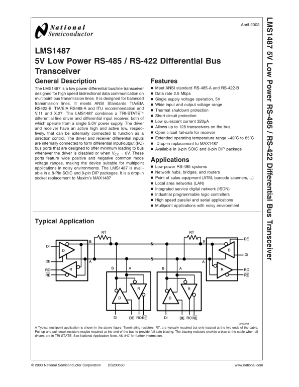
Typical multipoint application is shown in the above figure. Terminating resistors, RT, are typically required but only located at the two ends of the cable. Pull up and pull down resistors maybe required at the end of the bus to provide fail-safe biasing. The biasing resistors provide bias to the cable when all drivers are in TRI-STATE, See National Application Note, AN-847 for further information.
National Semiconductor Corporation DS200530 www.national.com
Page Summary Contents For NATIONAL SEMICONDUCTOR LMS1487 User Guide
Manual Details
| Brand | National |
|---|---|
| Pages | 13 |
| File Size | 249.84 KB |
| Published | May 30, 2026 |
Enter the captcha to get the download link:

Frequently Asked Questions
Are terminating resistors necessary when installing the LMS1487?
Yes, terminating resistors (RT) are typically required, and they should only be located at the two ends of the cable.
What voltage range is required for the power supply (V CC)?
The device requires a single 5.0V power supply operating in the range of 4.75V to 5.25V.
Can this be used as a replacement for older devices?
Yes, it is designed as a drop-in replacement for MAX1487 bus ports and socket replacements for applications like POS equipment.