# A B C D E F G H I J K L M N O P Q R S T U V W X Y Z

NATIONAL SEMICONDUCTOR LM5000 User Guide

Summary

This high-voltage switch mode regulator IC is a versatile component designed for reliable power conversion in flyback, boost, and forward architectures. It supports a wide input voltage range of 3.1V to 40V and incorporates advanced safety features like overcurrent protection and softstart. The accompanying manual provides engineers with comprehensive technical specifications, detailed operating modes, and application guidelines needed for circuit design. It is ideal for professionals developing regulated power systems in areas such as DSL modems or distributed power converters.
📄 Preview 📖 Table of Contents Contents PAGE OF 18

Page 1 Text Content

ig lta itc la to

February 2007

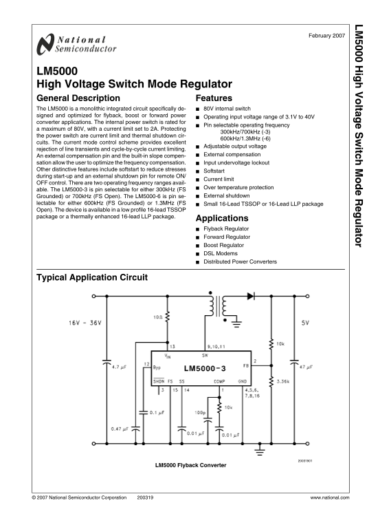
LM5000 High Voltage Switch Mode Regulator General Description Features The LM5000 is a monolithic integrated circuit specifically de- 80V internal switch signed and optimized for flyback, boost or forward power

Operating input voltage range of 3.1V to 40V

converter applications. The internal power switch is rated for

Pin selectable operating frequency

a maximum of 80V, with a current limit set to 2A. Protecting

300k Hz/700k Hz (-3)

the power switch are current limit and thermal shutdown cir-

600k Hz/1.3MHz (-6)

cuits. The current mode control scheme provides excellent

Adjustable output voltage

rejection of line transients and cycle-by-cycle current limiting.

External compensation

An external compensation pin and the built-in slope compen- sation allow the user to optimize the frequency compensation. Input undervoltage lockout Other distinctive features include softstart to reduce stresses

Softstart

during start-up and an external shutdown pin for remote ON/

Current limit

OFF control. There are two operating frequency ranges avail-

Over temperature protection

able. The LM5000-3 is pin selectable for either 300k Hz (FS

Grounded) or 700k Hz (FS Open). The LM5000-6 is pin se- External shutdown

lectable for either 600k Hz (FS Grounded) or 1.3MHz (FS Small 16-Lead TSSOP or 16-Lead LLP package Open). The device is available in a low profile 16-lead TSSOP package or a thermally enhanced 16-lead LLP package.

Applications Flyback Regulator Forward Regulator Boost Regulator DSL Modems Distributed Power Converters

Typical Application Circuit

LM5000 Flyback Converter

© 2007 National Semiconductor Corporation www.national.com

Page Summary Contents For NATIONAL SEMICONDUCTOR LM5000 User Guide

Page 1 ig lta itc la to February 2007 LM5000 High Voltage Switch Mode Regulator General Description Features The LM5000 is a monolithic integrated circuit specifically de- 80V internal switch signed and opti...
Page 2 Connection Diagram Top View Ordering Information Order Number Package Type NSC Package Drawing Supplied As LM5000-3MTC TSSOP-16 MTC16 94 Units, Rail LM5000-3MTCX TSSOP-16 MTC16 2500 Units, Tape and Re...
Page 3 Infrared (15 sec.) 235°C Absolute Maximum Ratings (Note 1) ESD Susceptibility (Note 3) If Military/Aerospace specified devices are required, Human Body Model 2k V please contact the National Semicondu...
Page 4 Min Typ Max Symbol Parameter Conditions Units (Note 4) (Note 5) (Note 4) θJA Thermal Resistance TSSOP, Package only °C/W LLP, Package only Note 1: Absolute maximum ratings are limits beyond which dama...
Page 5 Typical Performance Characteristics Iq (non-switching) vs VIN @ f SW = 300k Hz Iq (non-switching) vs VIN @ f SW = 700k Hz Iq (switching) vs VIN @ f SW = 300k Hz Iq (switching) vs VIN @ f SW = 700k Hz ...
Page 6 Current Limit vs Temperature Current Limit vs VIN f SW vs. VIN @ FS = Low (-3) f SW vs. VIN @ FS = OPEN (-3) f SW vs. Temperature @ FS = Low (-3) f SW vs. Temperature @ FS = OPEN (-3) www.national.com
Page 7 f SW vs. Temperature @ FS = Low (-6) f SW vs. Temperature @ FS = OPEN (-6) Error Amp. Transconductance vs Temp. BYP Pin Voltage vs VIN www.national.com
Page 8 FIGURE 1. 300 k Hz operation, 48V output FIGURE 2. 700 k Hz operation, 48V output www.national.com
Page 9 Block Diagram end of the period and current flows through the inductor once Boost Regulator Operation again. The LM5000 utilizes a PWM control scheme to regulate the The LM5000 has dedicated protectio...
Page 10 Operation FIGURE 3. Simplified Boost Converter Diagram (a) First Cycle of Operation (b) Second Cycle Of Operation CONTINUOUS CONDUCTION MODE INTRODUCTION TO COMPENSATION The LM5000 is a current-mode, ...
Page 11 Figure 4 (a)). If the slope of the inductor current is too great, loop system that must be stabilized to avoid positive feedback the circuit will be unstable above duty cycles of 50%. and instability....
Page 12 where RO is the output impedance of the error amplifier, 850kΩ. Since RC is generally much less than RO, it does not have much effect on the above equation and can be neglected until a value is chosen...
Page 13 OUTPUT VOLTAGE LIMITATIONS Flyback Regulator Operation The maximum output voltage of a boost regulator is the max- The LM5000 is ideally suited for use in the flyback regulator imum switch voltage min...
Page 14 ITEM PART NUMBER DESCRIPTION VALUE C4532X7R2A105MT Capacitor, CER, TDK 1µ, 100V C4532X7R2A105MT Capacitor, CER, TDK 1µ, 100V C1206C224K5RAC Capacitor, CER, KEMET 0.22µ, 50V C1206C104K5RAC Capacitor, C...
Page 15 Physical Dimensions inches (millimeters) unless otherwise noted TSSOP-16 Pin Package (MTC) For Ordering, Refer to Ordering Information Table NS Package Number MTC16 www.national.com
Page 16 LLP-16 Pin Package (SDA) For Ordering, Refer to Ordering Information Table NS Package Number SDA16A www.national.com
Page 17 Notes www.national.com
Page 18 ig lt it la to Notes THE CONTENTS OF THIS DOCUMENT ARE PROVIDED IN CONNECTION WITH NATIONAL SEMICONDUCTOR CORPORATION (“NATIONAL”) PRODUCTS. NATIONAL MAKES NO REPRESENTATIONS OR WARRANTIES WITH RESPEC...

Manual Details

Brand National
Pages 18
File Size 388.25 KB
Published June 17, 2026
4 views

Enter the captcha to get the download link:

captcha

Frequently Asked Questions

How must I connect the COMP compensation network pin?

Connect it from this pin to AGND, and an additional 100pF high frequency capacitor to AGND is recommended.

What are my options for selecting the operating switching frequency?

The device allows selectable frequencies of 300kHz, 600kHz, or 1.3MHz using the FS input pin.

Can this regulator be used in life support applications?

No. It is not authorized for use as critical components in life support systems without prior written approval from National Semiconductor Corporation.

How can I control the start-up and shutdown of the device?

Use the Softstart input to reduce stress during startup, and an external shutdown pin (SHDN) for remote ON/OFF control.