# A B C D E F G H I J K L M N O P Q R S T U V W X Y Z

National LM1577 LM2577 User's Manual

Summary

The LM1577/LM2577 are high-efficiency step-up voltage regulators designed as monolithic integrated circuits for electronic designers. They provide robust boost, flyback, and forward conversion with wide input ranges (3.5V–40V) while requiring minimal external components. This technical manual provides comprehensive details on electrical characteristics, operating parameters across various temperatures, available packages (DIP, TO-220, etc.), and connection diagrams. It is essential reading for engineers seeking reliable, adjustable DC/DC power solutions.
📄 Preview PAGE OF 31

Page 1 Text Content

April

LM 1577/LM IM LE ITC tep-U Voltage egulator

LM1577/LM2577 SIMPLE SWITCHER® Step-Up Voltage Regulator General Description Features

The LM1577/LM2577 are monolithic integrated circuits that Requires few external components provide all of the power and control functions for step-up NPN output switches 3.0A, can stand off 65V

(boost), flyback, and forward converter switching regulators. Wide input voltage range: 3.5V to 40V The device is available in three different output voltage

Current-mode operation for improved transient

versions: 12V, 15V, and adjustable.

response, line regulation, and current limit

Requiring minimum number of external components, these k Hz internal oscillator regulators are cost effective, and simple to use. Listed in this

Soft-start function reduces in-rush current during start-up

data sheet are family of standard inductors and flyback

Output switch protected by current limit, under-voltage

transformers designed to work with these switching regula-

lockout, and thermal shutdown

tors. Included on the chip is 3.0A NPN switch and its associated

Typical Applications

protection circuitry, consisting of current and thermal limiting,

Simple boost regulator

and undervoltage lockout. Other features include k Hz

Flyback and forward regulators

fixed-frequency oscillator that requires no external compo-

nents, soft start mode to reduce in-rush current during Multiple-output regulator

start-up, and current mode control for improved rejection of input voltage and output load transients.

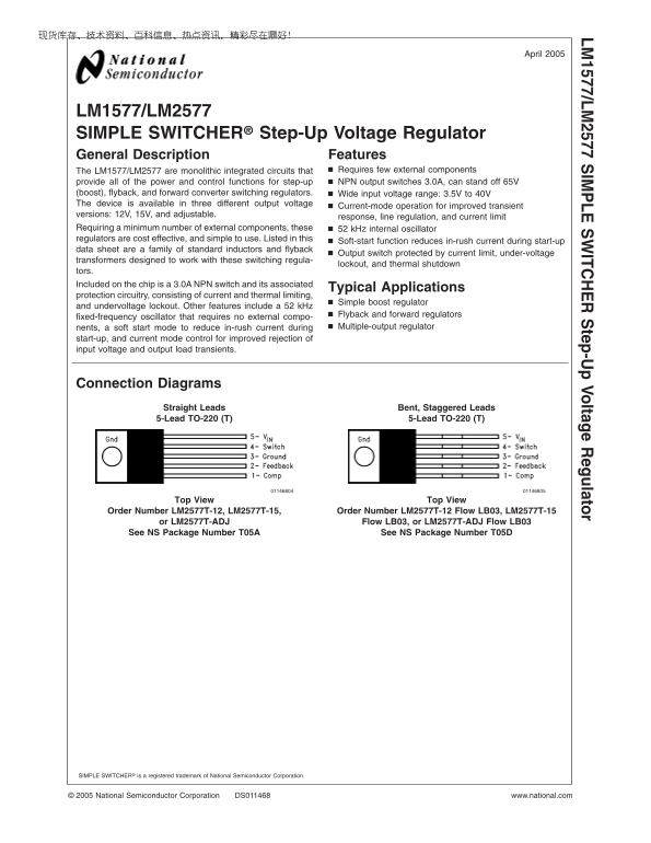
Connection Diagrams

Straight Leads Bent, Staggered Leads 5-Lead TO-220 (T) 5-Lead TO-220 (T)

View View

Order Number LM2577T-12, LM2577T-15, Order Number LM2577T-12 Flow LB03, LM2577T-15

or LM2577T-ADJ Flow LB03, or LM2577T-ADJ Flow LB03 See NS Package Number T05A See NS Package Number T05D

SIMPLE SWITCHER® is registered trademark of National Semiconductor Corporation.

National Semiconductor Corporation DS011468 www.national.com

Page Summary Contents For National LM1577 LM2577 User's Manual

Page 1 April LM 1577/LM IM LE ITC tep-U Voltage egulator LM1577/LM2577 SIMPLE SWITCHER® Step-Up Voltage Regulator General Description Features The LM1577/LM2577 are monolithic integrated circuits that Requir...
Page 2 Connection Diagrams (Continued) LM /L 16-Lead DIP (N) 24-Lead Surface Mount (M) *No internal Connection Order Number LM2577N-12, LM2577N-15, or LM2577N-ADJ See NS Package Number N16A *No internal Conn...
Page 3 Ordering Information LM 1577/LM Temperature Package Output Voltage NSC Range Type 12V 15V ADJ Package Package Drawing −40˚C TA +125˚C 24-Pin Surface LM2577M-12 LM2577M-15 LM2577M-ADJ M24B SO Mount 16-...
Page 4 Absolute Maximum Ratings (Note 1) Minimum ESD Rating If Military/Aerospace specified devices are required, (C p F, 1.5 kΩ) k V LM /L please contact the National Semiconductor Sales Office/ Distributor...
Page 5 Electrical Characteristics—LM1577-12, LM2577-12 (Continued) LM 1577/LM Specifications with standard type face are for TJ 25˚C, and those in bold type face apply over full Operating Temperature Range. ...
Page 6 Electrical Characteristics—LM1577-15, LM2577-15 (Continued) Specifications with standard type face are for TJ 25˚C, and those in bold type face apply over full Operating Temperature LM /L Range. Unles...
Page 7 Electrical Characteristics—LM1577-15, LM2577-15 (Continued) LM 1577/LM Specifications with standard type face are for TJ 25˚C, and those in bold type face apply over full Operating Temperature Range. ...
Page 8 Electrical Characteristics—LM1577-ADJ, LM2577-ADJ (Continued) Specifications with standard type face are for TJ 25˚C, and those in bold type face apply over full Operating Temperature LM /L Range. Unl...
Page 9 Electrical Characteristics—LM1577-ADJ, LM2577-ADJ (Continued) LM 1577/LM Note 8: Junction to ambient thermal resistance with approximately square inch of pc board copper surrounding the leads. Additio...
Page 10 Typical Performance Characteristics (Continued) LM /L Error Amp Transconductance Error Amp Transconductance vs Temperature vs Temperature Error Amp Transconductance Error Amp Voltage vs Temperature Ga...
Page 11 Typical Performance Characteristics (Continued) LM 1577/LM Quiescent Current Quiescent Current vs Temperature vs Switch Current Current Limit Current Limit Response vs Temperature Time vs Overdrive Sw...
Page 12 Typical Performance Characteristics (Continued) LM /L Feedback Pin Bias Oscillator Frequency Current vs Temperature vs Temperature Maximum Power Dissipation (TO-263) (Note 9) www.national.com
Page 13 LM1577-12, LM2577-12 Test Circuit LM 1577/LM 415-0930 (AIE) any manufacturer COUT Sprague Type 673D Electrolytic µF, 20V Note: Pin numbers shown are for TO-220 (T) package FIGURE 1. Circuit Used to Sp...
Page 14 LM1577-ADJ, LM2577-ADJ Test Circuit LM /L 415-0930 (AIE) any manufacturer COUT Sprague Type 673D Electrolytic µF, 20V R1 48.7k in series with 511Ω (1%) R2 5.62k (1%) Note: Pin numbers shown are for TO...
Page 15 Application Hints (Continued) LM 1577/LM Duty Cycle STEP-UP (BOOST) REGULATOR Figure shows the LM1577-ADJ/LM2577-ADJ used as Average Step-Up Regulator. This is switching regulator used for producing a...
Page 16 Application Hints 1. Find the lowest value inductor that is greater than LMIN. (Continued) 2. Find where E•T intersects this inductor value to determine LM /L ditions for which the LM1577/LM2577 outpu...
Page 17 Application Hints (Continued) LM 1577/LM Note: These charts assume that the inductor ripple current inductor is approximately 20% to 30% of the average inductor current (when the regulator is under fu...
Page 18 Application Hints C. Calculate the minimum value of CC (Continued) LM /L Inductor Manufacturer’s Part Number Code Schott Pulse Renco L47 PE RL2442 The compensation capacitor is also part of the soft s...
Page 19 Application Hints (Continued) If the LM1577 is located far from the supply source filter LM 1577/LM 3. Output Voltage Selection (R1 and R2) capacitors, an additional large electrolytic capacitor (e.g....
Page 20 Application Hints (Continued) LM /L Note: Pin numbers shown are for TO-220 (T) package. FIGURE 13. Step-up Regulator Delivers 12V from 5V Input FIGURE 14. Line Regulation (Typical) of Step-Up Regulato...
Page 21 Application Hints A. First, calculate the maximum value for RC. (Continued) LM 1577/LM FLYBACK REGULATOR Flyback regulator can produce single or multiple output voltages that are lower or greater than...
Page 22 Application Hints (Continued) LM /L T1 Pulse Engineering, PE-65300 D1, D2 1N5821 FIGURE 18. LM1577-ADJ/LM2577-ADJ Flyback Regulator with Outputs www.national.com
Page 23 Application Hints (Continued) LM 1577/LM Duty Cycle Primary Current Variation Peak Primary Current IP(PK) Switch Voltage when Off VSW(OFF) Diode Reverse Voltage VR VOUT (VIN VSAT) Average Diode Curren...
Page 24 Application Hints ber consists of fast recovery diode, and parallel RC. The (Continued) RC values are selected for switch clamp voltage (VCLAMP) LM /L step-up regulator, and this requires larger bypas...
Page 25 Application Hints (Continued) LM 1577/LM T1 Pulse Engineering, PE-65300 D1, D2 1N5821 FIGURE 22. Flyback Regulator Easily Provides Dual Outputs A: Output Voltage Change, m V/div B: Output Current, m A...
Page 26 Application Hints (Continued) LM /L A: Output Voltage Change, m V/div B: Output Current, m A/div Horizontal: ms/div FIGURE 26. Load Transient Response of Flyback Regulator of Figure 22, −15V Output FI...
Page 27 Physical Dimensions inches (millimeters) LM 1577/LM unless otherwise noted TO-3 Metal Can Package (K) Order Number LM1577K-12/883, LM1577K-15/883, or LM1577K-ADJ/883 NS Package Number K04A 0.300 Wide ...
Page 28 Physical Dimensions inches (millimeters) unless otherwise noted (Continued) LM /L Molded Dual-In-Line Package (N) Order Number LM2577N-12, LM2577N-15, or LM2577N-ADJ NS Package Number N16A TO-220, Str...
Page 29 Physical Dimensions inches (millimeters) unless otherwise noted (Continued) LM 1577/LM TO-220, Bent Staggered Leads (T) Order Number LM2577T-12 Flow LB03, LM2577T-15 Flow LB03, or LM2577T-ADJ Flow LB0...
Page 30 Physical Dimensions inches (millimeters) unless otherwise noted (Continued) LM /L IM LE IT te p- Vo lta ge eg ul at or 5-Lead TO-263 (S) Order Number LM2577S-12, LM2577S-15 or LM2577S-ADJ NS Package N...
Page 31 LM 1577/LM IM LE ITC tep-U Voltage egulator Tel: 81-3-5639-7560www.national.com

Manual Details

Brand National
Pages 31
File Size 1.36 MB
Published May 27, 2026
104 views

Enter the captcha to get the download link:

captcha

Frequently Asked Questions

What is the wide input voltage range for this regulator?

The LM1577/LM2577 supports a wide input voltage range of 3.5V to 40V.

What advanced controls are included for improved stability?

It features current-mode control, line regulation, and current limit protection for stable operation.

How do I reduce in-rush current during startup?

Using the soft-start function will help reduce the in-rush current when the regulator is powered on.

What maximum voltage can the output switch handle?

The device includes an NPN output switch capable of standing off up to 65V.