Page 1
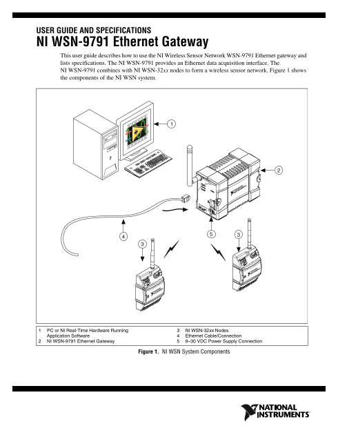
USER GUIDE AND SPECIFICATIONS NI WSN-9791 Ethernet Gateway This user guide describes how to use the NI Wireless Sensor Network WSN-9791 Ethernet gateway and lists specifications. The NI WSN-9791 provi...
Page 2
Figure 2 shows a close up of the NI WSN-9791. Figure 2. NI WSN-9791 Ethernet Gateway Dimensions Figure 3 shows the NI WSN-9791 device dimensions. 146.88 mm (5.783 in.) 87.50 mm (3.445 in.) 51.29 mm 11...
Page 3
Safety Guidelines Operate the NI WSN-9791 only as described in this user guide. Hot Surface This icon denotes that the component may be hot. Touching this component may result in bodily injury. NI WSN...
Page 4
levels, special equipment, limited-energy parts of equipment, circuits powered by regulated low-voltage sources, and electronics. Installation Category II is for measurements performed on circuits dir...
Page 5
Electromagnetic Compatibility Guidelines This product was tested and complies with the regulatory requirements and limits for electromagnetic compatibility (EMC) as stated in the product specification...
Page 6
Software Overview Note Refer to the NI WSN Readme, available on the software installation disc included with your device, for NI software application version support. The NI-WSN software includes NI M...
Page 7
Unpack the Devices and Install the Antenna Remove the devices from the package and inspect the device. Contact NI if the device appears damaged. Do not install a damaged device. Caution The device is ...
Page 8
Note Figure 5 is an actual size template. You can print it out and use it to determine screw hole placement for panel mounting. (0 .1 in (0 .1 in 101.60 mm (4.000 in.) 4. (4 .5 in 55.88 mm 45.72 mm (2...
Page 9
Using the Integrated Panel Mount Feature The NI WSN-9791 integrated panel mount feature accepts number 8 or M4 pan head screws to secure the device onto a flat surface. To install the NI WSN-9791 on a...
Page 10
Attaching to the NI WSN-3282 DIN Rail Caution Power off the device before mounting it to the DIN rail. The NI WSN-3282 DIN rail kit, NI part number 781074-01, contains one clip for mounting the device...
Page 11
Attaching to the NI WSN-3283 Panel Mount Plate The NI WSN-3283 panel mount kit, NI part number 781075-01, contains a plate for mounting the device to a panel. To mount the device, complete the followi...
Page 12
Setting Up the NI WSN-9791 Device Complete the following steps to prepare the NI WSN-9791 device for use: 1. Before connecting the hardware, install NI Lab VIEW and the NI-WSN driver software. You mus...
Page 13
Device Interface Figure 11 shows the NI WSN-9791 device interface. NI WSN-9791 Antenna RP-SMA Connector 9–30 VDC Power Connector RESET Button LEDs: ACTIVITY, STATUS, and POWER RJ45 Ethernet Port, 10/1...
Page 14
Table 1. LED State/Device Status (Continued) LED Description Color LED State Device Status STATUS Yellow On Device firmware booting or resetting to factory default Off Normal operation 1 Blink Radio e...
Page 15
NI Wireless Sensor Networks The NI WSN system is built on an IEEE 802.15.4 wireless mesh network. The 802.15.4 radio in each NI WSN device provides for low-power communication of measurement data acro...
Page 16
Since each node joins a network instead of a particular router or gateway, it can find a new path back to the gateway in the event that the signal is lost or blocked to its existing network route. In ...
Page 17
In this configuration, R1 (a router) and R2 (a router) both communicate directly with the gateway. Measurements taken by both devices can directly reach the gateway without having to hop through anoth...
Page 18
In this configuration, R1 can still communicate with the gateway, but R2 is now connected through R1. This means that all measurements taken by R2 must hop through R1 before making it back to the gate...
Page 19
Another advantage of the mesh network is the ability to extend the distance of the end measurement from the wired Ethernet gateway. By placing mesh routers throughout the space where you wish to acqui...
Page 20
Configuring Your NI WSN System As discussed in the Mesh Networking section, creating a reliable and efficient wireless sensor network requires an understanding of the physical environment the network ...
Page 21
In this case, all nodes have properly meshed, and all nodes can communicate with the gateway. However, this network could potentially strand end nodes. Figure 17 shows another possible mesh of the sam...
Page 22
Specifications These specifications are typical at 25 °C unless otherwise noted. For the NI WSN-32xx specifications, refer to the device user guides. Wireless Characteristics Radio mode .................
Page 23
Power Requirements Caution You must use a UL Listed ITE power supply marked LPS with the NI WSN-9791. The power supply must also meet any safety and compliance requirements for the country of use. Inp...
Page 24
RF Safety Warning This product complies with FCC radiation exposure limits set for uncontrolled equipment and meets the FCC radio frequency (RF) Exposure Guidelines in Supplement C to OET65. This prod...
Page 25
Europe—EU Declaration of Conformity Marking by the above CE symbol on the label indicates compliance with the Essential Requirements of the R&TTE Directive of the European Union (1999/5/EC). This ...
Page 26
Taiwan R.O.C. 低功率電波輻射性電機管理辦法 第十二條經型式認證合格之低功率射頻電機,非經許可,公司、商號或使 用者均不得擅自變更頻率、加大功率或變更原設計之特性及功能。 第十四條低功率射頻電機之使用不得影響飛航安全及幹擾合法通信;經發 現有幹擾現象時,應立即停用,並改善至無幹擾時方得繼續使用。 前項合法通信,指依電信規定作業之無線電信。低功率射頻電機須忍受合法通信 或工業、科學及醫療...
Page 27
Polski Niniejszym National Instruments. oświadcza, że NI WSN-9791 jest zgodny z zasadniczymi [Polish] wymogami oraz pozostałymi stosownymi postanowieniami Dyrektywy 1999/5/EC. Português National Instr...
Page 28
Environmental Management National Instruments is committed to designing and manufacturing products in an environmentally responsible manner. NI recognizes that eliminating certain hazardous substances...
Page 29
Where to Go for Support National Instruments corporate headquarters is located at 11500 North Mopac Expressway, Austin, Texas, 78759-3504. National Instruments also has offices located around the worl...