JVC DX-T9 T7 T5 User Guide and Manual
Summary
This comprehensive technical manual provides professional service instructions for the DVD Changer Mechanism Assembly designed for various electronic playback devices. It guides skilled technicians through complete disassembly procedures, covering component removal of complex servo boards and switch assemblies. The guide includes critical steps for mechanism adjustment, detailed troubleshooting workflow, and specialized tips for safely servicing all parts, ensuring accurate repair of your player's core reading function.
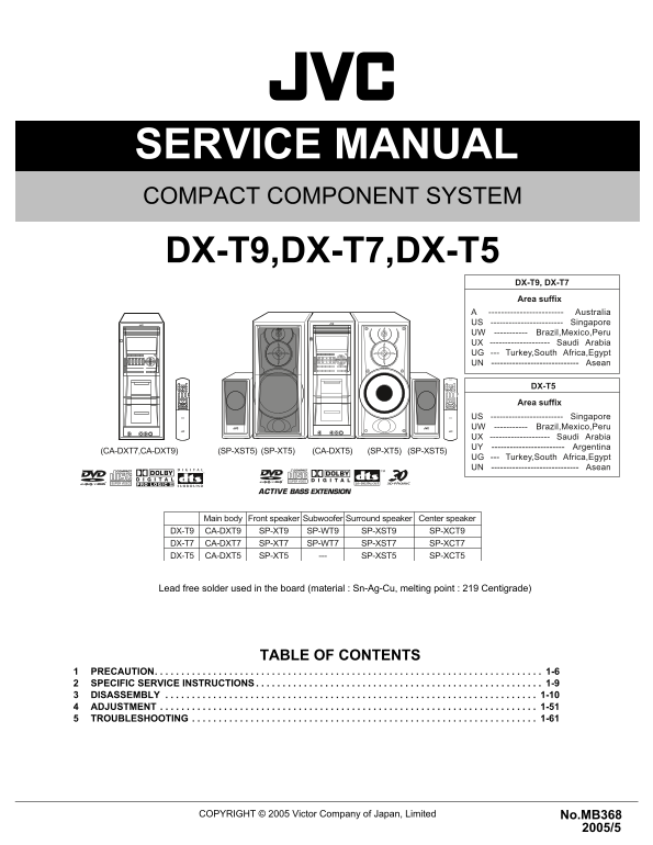
Page 1 Text Content
SERVICE MANUAL COMPACT COMPONENT SYSTEM MB36820055 DX-T9,DX-T7,DX-T5
DX-T9, DX-T7 Area suffix
A ------------------------ Australia US ------------------------ Singapore UW ----------- Brazil,Mexico,Peru UX -------------------- Saudi Arabia UG --- Turkey,South Africa,Egypt UN ----------------------------- Asean
DX-T5 Area suffix
US ------------------------ Singapore UW ----------- Brazil,Mexico,Peru UX -------------------- Saudi Arabia UY ------------------------ Argentina
(CA-DXT5) (SP-XT5)(SP-XST5)(CA-DXT7,CA-DXT9) (SP-XST5)(SP-XT5)
UG --- Turkey,South Africa,Egypt UN ----------------------------- Asean
Main body Front speaker Subwoofer Surround speaker Center speaker DX-T9 CA-DXT9 SP-XT9 SP-WT9 SP-XST9 SP-XCT9 DX-T7 CA-DXT7 SP-XT7 SP-WT7 SP-XST7 SP-XCT7 DX-T5 CA-DXT5 SP-XT5 SP-XST5 SP-XCT5
Lead free solder used in the board (material : Sn-Ag-Cu, melting point : 219 Centigrade)
TABLE OF CONTENTS
PRECAUTION. . . . . . . . . . . . . . . . . . . . . . . . . . . . . . . . . . . . . . . . . . . . . . . . . . . . . . . . . . . . . . . . . . . . . . . . . 1-6 SPECIFIC SERVICE INSTRUCTIONS . . . . . . . . . . . . . . . . . . . . . . . . . . . . . . . . . . . . . . . . . . . . . . . . . . . . . . 1-9 DISASSEMBLY . . . . . . . . . . . . . . . . . . . . . . . . . . . . . . . . . . . . . . . . . . . . . . . . . . . . . . . . . . . . . . . . . . . . . . 1-10 ADJUSTMENT . . . . . . . . . . . . . . . . . . . . . . . . . . . . . . . . . . . . . . . . . . . . . . . . . . . . . . . . . . . . . . . . . . . . . . . 1-51 TROUBLESHOOTING . . . . . . . . . . . . . . . . . . . . . . . . . . . . . . . . . . . . . . . . . . . . . . . . . . . . . . . . . . . . . . . . . 1-61
COPYRIGHT © 2005 Victor Company of Japan, Limited No.MB368
Page Summary Contents For JVC DX-T9 T7 T5 User Guide and Manual
Manual Details
| Brand | JVC |
|---|---|
| Pages | 16 |
| File Size | 641.73 KB |
| Published | May 24, 2026 |
Enter the captcha to get the download link:

Frequently Asked Questions
How should I handle the DVD pickup wiring before disconnecting it?
You must solder the short land sections 'd' on the DVD pickup first to prevent damage.
What is used in the main body board assembly soldering?
Lead-free solder (Sn-Ag-Cu) with a melting point of 219 Centigrade is used.
Where should the wires for reassembly be passed when removing the switch board?
The wires must pass through sections 'f' and 'g' during removal, and reassembled through those same sections.
Which parts need to be removed to take out the disc in play mode?
Remove the top cover, unlock/draw out tray assemblies, then use gears 1 and 2 sequentially.