# A B C D E F G H I J K L M N O P Q R S T U V W X Y Z

JVC BR-DV600U Video Cassette Recorder User's Manual and Specifications

Summary

The BR-DV600U/BR-DV600E is a professional video cassette recorder designed for reliable performance in commercial, industrial, and high-end residential settings. This comprehensive manual provides detailed instructions on advanced operation, covering everything from basic recording and playback controls to complex functions like Sub Scene Finder data management for integrating with non-linear editing systems. It serves as the essential guide for operators, ensuring correct setup, signal handling, and adhering to all critical usage and safety guidelines for optimal performance.
📄 Preview PAGE OF 24

Page 1 Text Content

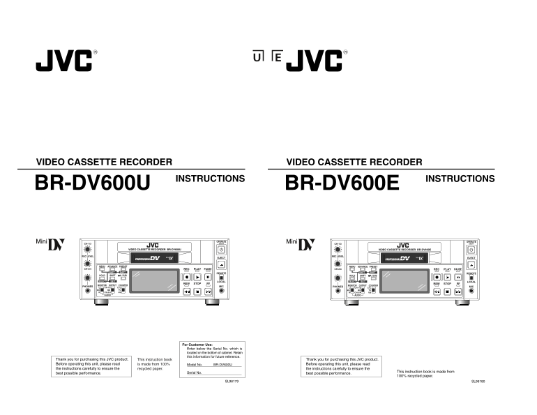
VIDEO CASSETTE RECORDER VIDEO CASSETTE RECORDER

INSTRUCTIONS INSTRUCTIONS

BR-DV600U BR-DV600E

OPERATE OPERATE CH-1/3 ON/OFF CH-1/3 ON/OFF

VIDEO CASSETTE RECORDER BR-DV600U VIDEO CASSETTE RECORDER BR-DV600E

REC LEVEL REC LEVEL

EJECT EJECT

MENU ADVANCE PRESET MENU ADVANCE PRESET

CH-2/4 REC PLAY PAUSE CH-2/4 REC PLAY PAUSE

SHIFT SHIFT REMOTE SHIFT SHIFT REMOTE

HOLD SHIFT A. DUB HOLD SHIFT A. DUB

SETSELECT LOCAL SETSELECT LOCAL

REW STOP FF REW STOP FF

PHONES MONITOR OUTPUT COUNTER MIC PHONES MONITOR OUTPUT COUNTER MIC

CH-1/2 CTL CH-1/2 CTL

MIX MIX TC MIX MIX TC CH-3/4R UB CH-3/4R UB

AUDIO AUDIO

For Customer Use: Enter below the Serial No. which is located on the bottom of cabinet. Retain this information for future reference.

Thank you for purchasing this JVC product. This instruction book Thank you for purchasing this JVC product. Before operating this unit, please read is made from 100% Model No. BR-DV600U Before operating this unit, please read the instructions carefully to ensure the recycled paper. the instructions carefully to ensure the

Serial No. This instruction book is made from

best possible performance. best possible performance.

100% recycled paper.

SL96179 SL96180

Page Summary Contents For JVC BR-DV600U Video Cassette Recorder User's Manual and Specifications

Page 1 VIDEO CASSETTE RECORDER VIDEO CASSETTE RECORDER INSTRUCTIONS INSTRUCTIONS BR-DV600U BR-DV600E OPERATE OPERATE CH-1/3 ON/OFF CH-1/3 ON/OFF VIDEO CASSETTE RECORDER BR-DV600U VIDEO CASSETTE RECORDER BR-D...
Page 2 Supplement This equipment is in conformity with the provisions and protection requirements of the corresponding European Directives. This equipment is designed for professional video appliances and ca...
Page 3 SAFETY PRECAUTIONS SAFETY PRECAUTIONS Warning Notice POWER SYSTEM CAUTION ATTENTION FOR YOUR SAFETY (Australia) Connection to the mains supply RISK OF ELECTRIC SHOCK RISQUE D’ELECTROCUTION DO NOT OPEN...
Page 4 For servicing See the service manual page 2-5 “2.4 MAIN TENANCE AND INSPECTION OF MAJOR PARTS”.→ CONTENTS 1 INTRODUCTION INTRODUCTION PLAYBACK 1-1 Major Features 1-1 Major Features Playback preparatio...
Page 5 1 INTRODUCTION 2 CONTROLS, CONNECTORS AND DISPLAYS 1-3 Precautions 2-1 Front Panel Installation and storage Cassette tape Avoid using the unit in places subject to the following Type OPERATE CH-1/3 ON...
Page 6 2 CONTROLS, CONNECTORS AND DISPLAYS 2 CONTROLS, CONNECTORS AND DISPLAYS 2-2 Rear Panel 2-3 On-Screen Display The on-screen display can be viewed on a monitor connected to the rear panel’s [VIDEO MONIT...
Page 7 2 CONTROLS, CONNECTORS AND DISPLAYS 3 CONNECTIONS 2-4 LCD Display 3-1 Video system connections CH 1/3 OVER DEWAUTO OFF Indicators Video output from a VCR, etc. Sync signal generator, etc. Reference sy...
Page 8 3 CONNECTIONS 3 CONNECTIONS 3-2 Audio system connections 3-3 Other connections Audio output from a VCR, etc. DV Analog audio (2 channels) IN/OUT DV DV LINE COMPONENTVIDEO AUDIO IN/OUT CH 1/3 CH 2/4 LI...
Page 9 3 CONNECTIONS 3 CONNECTIONS 3-4 Editing system examples 3-4 Editing system examples The BR-DV600U can be used as a feeder for different video formats. Mixed S-VHS/VHS system This is an editing system ...
Page 10 For servicing See the service manual page 1-10 “1.6 SERVICE MENU”.→ 3 CONNECTIONS 4 MENU SWITCHES Edit adjust setting You can set menu switches using either the on-screen display or the counter displa...
Page 11 4 MENU SWITCHES 4 MENU SWITCHES 4-2 Menu switch details 4-2 Menu switch details For switch setting procedures, refer to “Menu switch setting (When the optional SA-K46 RS-232C interface q: Factory sett...
Page 12 4 MENU SWITCHES 5 PREPARATION Preparing this unit for recording or playback. 4-2 Menu switch details q: Factory setting CHARACTER V.POSITION OPERATE CH-1/3 ON/OFF (00): The number in the bracket shows...
Page 13 5 PREPARATION 6 RECORDING Built-in clock setting [REC LEVEL] control Time data is recorded in the sub code area of the tape during recording. In the Play mode, this data is read out and can be shown o...
Page 14 6 RECORDING 7 PLAYBACK [REC LEVEL] control OPERATE OPERATE CH-1/3 ON/OFF CH-1/3 ON/OFF VIDEO CASSETTE RECORDER BR-DV600U VIDEO CASSETTE RECORDER BR-DV600U [OPERATE] button REC LEVEL REC LEVEL EJECT EJ...
Page 15 8 EXTERNAL TIMER-START FUNCTION 9 TIME CODE (AUTOMATIC START-UP WITH POWER SUPPLY) The time code is recorded frame by frame together with the materials to be recorded on the tape. With this time code,...
Page 16 9 TIME CODE 9 TIME CODE Set the menu switches. ( See page 20.) OPERATE CH-1/3 ON/OFF Set the No. 414 <TCG SELECT> menu switch to “PRESET”. VIDEO CASSETTE RECORDER BR-DV600U Set the No. 415 <...
Page 17 10 SUPER SCENE FINDER FUNCTION 11 RS-232C INTERFACE The SSF data recorded on the tape with the GY-DV500U’s Super Scene Finder function can be read out by installing the optional SA-K46 RS-232C interfa...
Page 18 11 RS-232C INTERFACE 11 RS-232C INTERFACE 11-2 RS-232C specifications 11-3 RS-232C commands 9PIN D-Sub ASCII code table An optional RS-232C interface can be installed in this unit Preparation and conn...
Page 19 11 RS-232C INTERFACE 11 RS-232C INTERFACE Commands Description Setting (preset) commands B6 R-SHUTTLE Shuttle reverse play. The search speed is specified by sending the speed code data These commands ...
Page 20 11 RS-232C INTERFACE 11 RS-232C INTERFACE Contents of STATUS SENSE Fourth byte Contents of JVC STATUS SENSE Error-related commands Bit No. Status When the bit is 1 When the STATUS SENSE (DDH) command ...
Page 21 11 RS-232C INTERFACE 11 RS-232C INTERFACE Menu switch setting command Corresponding bit values Menu switch Corresponding bit values Menu switch DATA0 D1/D2 Set value DATA0 D1/D2 Set value No. No. ED M...
Page 22 For servicing See the service manual page 1-16 “1.7 WARNIGN CODES”.→ 12 TROUBLESHOOTING 12 TROUBLESHOOTING 12-1 Warning indicators Error contents Operation Solution On-screen display Counter display I...
Page 23 12 TROUBLESHOOTING 14 SPECIFICATIONS General Audio input 12-2 Other problems Power Line : –8 d Bs, 10 kΩ, unbalanced requirements : AC 120 V (U MODEL), Mic : –67 d Bs, 3 kΩ, unbalanced AC 220 – 240 V ...
Page 24 Note: (U MODEL) Vorsichtshinweise für die Verwendung des Kopfreinigungsbandes Deutsch Bitte beachten Sie bei der Verwendung des Kopfreinigungsbandes die folgenden Vorsichtshinweise. When setting menu ...

Manual Details

Brand JVC
Pages 24
File Size 1.10 MB
Published May 24, 2026
102 views

Enter the captcha to get the download link:

captcha

Frequently Asked Questions

What must be done before operating the unit?

You must read all instructions carefully and save them for later use.

Can I clean this appliance with liquid or aerosol cleaners?

No, do not use liquid cleaners or aerosol cleaners; use a damp cloth instead.

What is the clearance requirement for operation?

Ensure all slots and openings are unobstructed to prevent overheating.

Does this device require a special power outlet?

Yes, it requires a 3-wire grounding type plug and an appropriate grounded electrical outlet.