IDEAL 62-160 Tone Generator Instructions Manual
Summary
Essential for telecom professionals, this versatile Tone Generator facilitates comprehensive testing and tracing of communication lines and coaxial cables. The included manual provides detailed instructions covering connection methods, continuity checks, modular pairing status, and line polarity verification. Use it to confirm circuit integrity across various mediums—ideal for network technicians who require precise diagnostics when troubleshooting telephone and data infrastructure.
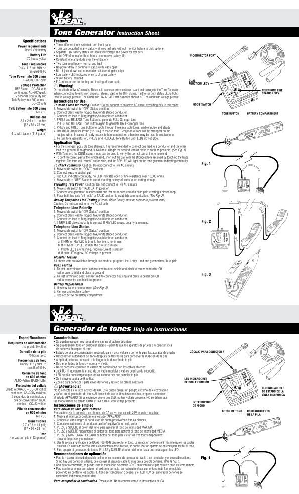
Page 1 Text Content
Tone Generator Instruction Sheet Specifications Features • Three different tones selected from front panel
Power requirements
• Tone can be added in any status – allows test sets without monitor feature to pick up tone
One 9 Volt battery TO
• Separate Talk Battery status for increased voltage and power for test sets 62-160 TO
Battery Life • Auto-OFF of tone after three hours to conserve battery life F-CONNECTOR PORT 70 hours typical • Constant tone amplitude over life of battery
Tone Frequencies • Two tone amplitude – normal and half Dual/1116 and 919 Hz, • No power draw in continuity status with leads open Single/919 Hz • RJ-11 jack allows use of modular cable or alligator clips FF FF
T S TATU TO T S TATU
TA ATT C LK TA ATT C LK
• Low battery LED indicates when to change battery TO . 62-160 ad e in in
Tone Power into 600 ohms
• 9 Volt battery included (HOLD) Dual
HI=7d Bm, LO=1d Bm DUAL HI Single
• F-Connector port for toning and tracing of coax cable
FUNCTION LED’s LO TA TA
Voltage Protection Warning! OFF Status – DC=58 volts Do not attach to live AC circuits. This could cause an extreme shock hazard and damage to the Tone Generator. NRM
TELEPh ONE LINE
continuous, AC=300Vpeak, When connecting to unknown circuits, always start in the OFF Status. If either or both status LEDS light, STATUS LED’s 2 seconds Continuity and there is voltage present. The CONT and TALK BATT status modes should NOT be used with voltage present. Talk Battery into 600 ohms –
Instructions for Use
DC=52 volts MODE SWITCh
To send a tone for tracing Caution: Do not connect to an active AC circuit exceeding 24V in this mode
Talk Battery into 600 ohms 1. Move slide switch to “OFF” Status position
6.0 VDC 2. Connect black lead to Tip/positive/white striped conductor.
TONE BUTTON BATTERY COMPARTMENT
3. Connect red lead to Ring/negative/solid colored conductor
Dimensions
4. PRESS and RELEASE Tone Button to generate FULL Strength tone
2.7 x 2.6 x 1.1 inches
5. PRESS and RELEASE Tone Button again to generate HALF-Strength tone
(67 x 66 x 28 mm)
6. PRESS and HOLD Tone Button to cycle through three available tones: warble, pulse and steady
Weight
7. Use IDEAL Amplifier Probe (62-164) to receive tone. Reception of tone will be strongest on the
4 oz with battery (113 grams)
subject wires. In cases of ready access to bare conductors, a handset may be used to receive tone. 8. To turn tone generator off, PRESS and RELEASE Tone Button until LEDs do not glow. Application Tips • For the strongest possible tone strength, it is recommended to connect one lead to a conductor and the other lead to a ground. If no ground is available, dangle the second lead as close to earth as possible. (See Fig. 1) • With Tone on, the CONT status mode can be used to verify the correct pair at the remote end. • To confirm correct pair at the remote end, short out the pair with the strongest tone received by touching the leads together. The tone will “cancel” out or stop, and the REV LED will light on the tone generator indicating continuity.
Fig. 1
To check continuity Caution: Do not connect to live AC circuits 1. Move slide switch to “CONT” position 2. Connect leads to subject pair 3. Red LED indicates continuity, no LED indicates open or line resistance over 10,000 ohms. 4. Move slide to “OFF” Status to avoid draining battery of leads touch during storage HI
Providing Talk Power Caution: Do not connect to live AC circuits
1. Move slide switch to “TALK BATT” position 2. Connect tone generator in series with one test set at each end of a dead pair, creating a closed loop. 3. Place both test sets “off hook” or TALK position to establish communication. (See Fig. 2) Analog Telephone Line Testing (Central Office Battery must be present to perform tests) Caution: Do not connect to to live AC circuits Telephone Line Polarity 1. Move slide switch to “OFF Status” position 2. Connect black lead to Tip/positive/white striped conductor. 3. Connect red lead to Ring/negative/solid colored conductor.
4. If NRM LED glows, polarity is correct. If REV LED glows, polarity is reversed. Fig. 2
Telephone Line Status 1. Move slide switch to “OFF Status” position
HI (HOLD) Dual
2. Connect black lead to Tip/positive/white striped conductor. Single LO
3. Connect red lead to Ring/negative/solid colored conductor.
a. If NRM or REV LED is bright, the line is not in use REV
b. If NRM or REV LED is dim, the circuit is in use c. If both LED’s are flashing, ringing current is present 2- d. If both LED’s glow, AC Voltage is present 2- Modular Testing All above tests are available through the modular plug for Line 1 only – red and green wires / blue pair Coax Testing 1. To test unterminated coax, connect red to outer shield and black to center conductor OR red to outer shield and black to ground
Fig. 3
2. To test terminated coax, connect red to connector housing and black to center pin OR red to connector and black to ground Battery Replacement 1. Unscrew battery compartment (See Fig. 3) 2. Remove and replace battery 3. Replace screw on battery compartment
Generador de tones Hoja de instrucciones Especificaciones Características • Se pueden escoger tres tonos diferentes en el tablero delantero
Requisitos de alimentación
• Se puede añadir tono en cualquier estado – permite que los aparatos de prueba sin característica
Una pila de 9 voltios
de supervisión capten el tono
Duración de la pila • Estado de pila de conversación separado para mayor voltaje y corriente para los aparatos de prueba ZÓCALO PARA CONECTOR F
70 horas típico • Desconexión automática del tono después de tres horas para conservar la duración de la pila
Frecuencias de tono • Amplitud de tonos constante a lo largo de la duración de la pila Doble/1116 y 919 Hz, • Dos amplitudes de tonos – normal y medio sencillo/919 Hz • No se consume corriente en estado de continuidad con los cables abiertos • Jack RJ-11 que permite el uso de un cable modular o cables de pinza de cocodrilo
Corriente de tono
• LED de pila poco cargada que indica cuándo hay que cambiar la pila Dual
en 600 ohmios (HOLD) • Se incluye una pila de 9 voltios LED INDICADORES HI Single ALTO=7d Bm, BAJO=1d Bm LO
• Zócalo para conector F para envío de tonos y rastreo de cables coaxiales DE DOBLE FUNCIÓN
Protección del voltaje ¡Advertencia!
LED INDICADORES
Estado APAGADO – CC=58 voltios REV
No lo conecte a circuitos activos de CA. Esto puede causar un peligro extremo de electrocución
DE ESTADO DE LA
continuos, CA=300V máximo, y daños en el generador de tonos Al conectarlo a circuitos desconocidos, empiece siempre en
LÍNEA TELEFÓNICA
2 segundos de continuidad y el estado APAGADO. Si se enciende uno o dos LED, no hay voltaje presente. NO se deben usar pila de conversación en600 las modalidades de estado CONT y TALK BATT con voltaje presente.
INTERRUPTOR
ohmios – CC=52 voltios
Instrucciones de empleo DE MODO
Pila de conversación Para enviar un tono para rastrear
BOTÓN DE TONO COMPARTIMIENTO
en 600 ohmios Precaución: No lo conecte a un circuito de CA activo que exceda 24V en esta modalidad
DE LA PILA
6,0 VCC 1. Mueva el interruptor deslizante al estado “APAGADO”
2. Conecte el cable negro al conductor de punta/positivo/con franjas blancas.
Dimensiones
3. Conecte el cable rojo al conductor anillo/negativo/de un solo color
2,7 x 2,6 x 1,1 pulg
4. PULSE y SUELTE el botón del tono para generar el tono de intensidad MÁXIMA
(67 x 66 x 28 mm)
5. PULSE y SUELTE nuevamente el botón del tono para generar el tono de intensidad MEDIA
6. PULSE y MANTENGA PULSADO el botón del tono para ciclar los tres tonos disponibles:
4 onzas con pila (113 gramos)
ululado, impulsos y constante 7. Use la sonda amplificadora de IDEAL (62-164) para recibir el tono. La recepción de tono será más intensa en los cables tratados. En casos de acceso listo a conductores descubiertos, se puede usar un aparato de pruebas para recibir el tono. 8. Para apagar el generador de tonos, PULSE y SUELTE el botón del tono hasta que se apaguen los LED. Recomendaciones de aplicación • Para la máxima intensidad posible del tono, se recomienda conectar un cable a un conductor y el otro cable a tierra. Fig. 1 Si no hay una conexión a tierra, deje colgar el segundo cable lo más cerca posible de tierra. (Vea la Fig. 1) • Con el tono conectado, se puede usar la modalidad de estado CONT para verificar el par correcto en el extremo remoto. • Para confirmar el par correcto en el extremo correcto, cortocircuite el par con el tono más fuerte recibido poniendo en contacto los cables. El tono se “cancelará” o cesará, y el LED REV del generador de tonos se
encenderá indicando continuidad. HI LO
Para comprobar la continuidad Precaución: No lo conecte con circuitos activos de CA. NRM REV
Page Summary Contents For IDEAL 62-160 Tone Generator Instructions Manual
Manual Details
| Brand | Ideal |
|---|---|
| Pages | 2 |
| File Size | 820.60 KB |
| Published | May 23, 2026 |
Enter the captcha to get the download link:

Frequently Asked Questions
What voltage level should I not connect this device to?
Do not attach it to live AC circuits, as high voltages can cause extreme shock hazards.
How do I check if a phone line pair has continuity?
Set the switch to 'CONT' and a red LED indicates continuity; no lit LED suggests an open circuit.
What is the maximum tone strength available for testing?
You must press and release the Tone Button once to generate full-strength tone.
How do I replace the internal battery?
Dévisser the battery compartment cover, remove the old battery, replace it with a new one, and reattach the lid.