Futaba GYA351 User's Manual
Summary
This guide introduces the GYA351, a high-performance, compact AVCS gyro designed for advanced model aircraft stabilization systems. Featuring an integrated SMM sensor and digital PI control, this unit maintains flight attitudes automatically, significantly enhancing maneuverability while correcting bad air tendencies. The manual provides comprehensive instructions on installation, system setup, operational modes (Normal and AVCS), and connecting all necessary components. Crucially, it delivers detailed safety warnings and guidelines for proper operation to ensure a safe and reliable flying experience for model aircraft enthusiasts.
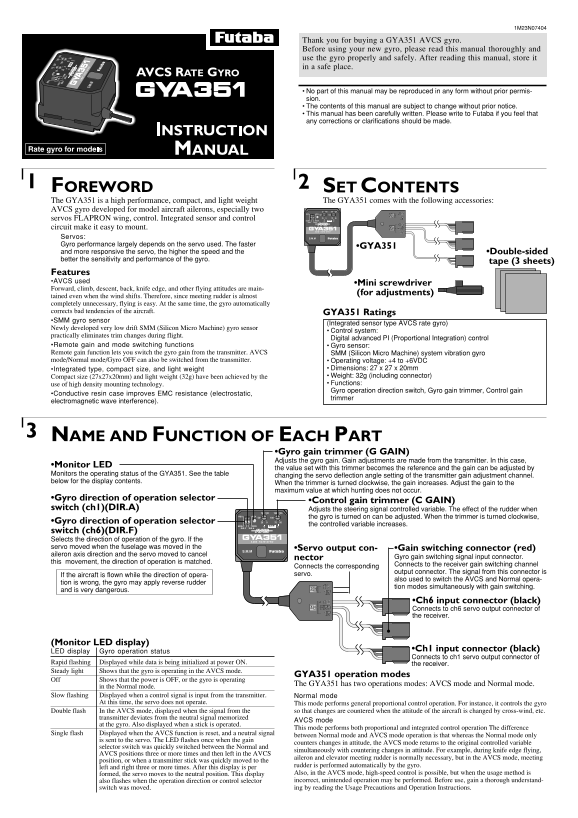
Page 1 Text Content
Thank you for buying a GYA351 AVCS gyro. Before using your new gyro, please read this manual thoroughly and use the gyro properly and safely. After reading this manual, store it in a safe place.
No part of this manual may be reproduced in any form without prior permis- sion. The contents of this manual are subject to change without prior notice. This manual has been carefully written. Please write to Futaba if you feel that any corrections or clarifications should be made.
FOREWORD1 SET CONTENTS2 The GYA351 is a high performance, compact, and light weight The GYA351 comes with the following accessories: AVCS gyro developed for model aircraft ailerons, especially two servos FLAPRON wing, control. Integrated sensor and control circuit make it easy to mount. Servos: Gyro performance largely depends on the servo used. The faster
•GYA351
and more responsive the servo, the higher the speed and the •Double-sided better the sensitivity and performance of the gyro.
tape (3 sheets)
Features •AVCS used
•Mini screwdriver
Forward, climb, descent, back, knife edge, and other flying attitudes are main-
(for adjustments)
tained even when the wind shifts. Therefore, since meeting rudder is almost completely unnecessary, flying is easy. At the same time, the gyro automatically corrects bad tendencies of the aircraft. GYA351 Ratings •SMM gyro sensor
(Integrated sensor type AVCS rate gyro)
Newly developed very low drift SMM (Silicon Micro Machine) gyro sensor
Control system:
practically eliminates trim changes during flight.
Digital advanced PI (Proportional Integration) control
•Remote gain and mode switching functions Gyro sensor: Remote gain function lets you switch the gyro gain from the transmitter. AVCS SMM (Silicon Micro Machine) system vibration gyro mode/Normal mode/Gyro OFF can also be switched from the transmitter. Operating voltage: +4 to +6VDC
•Integrated type, compact size, and light weight Dimensions: 27 x 27 x 20mm Compact size (27x27x20mm) and light weight (32g) have been achieved by the Weight: 32g (including connector) use of high density mounting technology. Functions: Gyro operation direction switch, Gyro gain trimmer, Control gain
•Conductive resin case improves EMC resistance (electrostatic,
trimmer
electromagnetic wave interference).
NAME AND FUNCTION OF EACH PART3
•Gyro gain trimmer (G GAIN) Adjusts the gyro gain. Gain adjustments are made from the transmitter. In this case,
•Monitor LED
the value set with this trimmer becomes the reference and the gain can be adjusted by
Monitors the operating status of the GYA351. See the table changing the servo deflection angle setting of the transmitter gain adjustment channel. below for the display contents. When the trimmer is turned clockwise, the gain increases. Adjust the gain to the
maximum value at which hunting does not occur.
•Gyro direction of operation selector
•Control gain trimmer (C GAIN)
switch (ch1)(DIR.A) Adjusts the steering signal controlled variable. The effect of the rudder when
the gyro is turned on can be adjusted. When the trimmer is turned clockwise,
•Gyro direction of operation selector
the controlled variable increases.
switch (ch6)(DIR.F) Selects the direction of operation of the gyro. If the servo moved when the fuselage was moved in the •Servo output con- •Gain switching connector (red) aileron axis direction and the servo moved to cancel
nector Gyro gain switching signal input connector.
this movement, the direction of operation is matched.
Connects to the receiver gain switching channel
Connects the corresponding
output connector. The signal from this connector is
If the aircraft is flown while the direction of opera- servo.
also used to switch the AVCS and Normal opera-
tion is wrong, the gyro may apply reverse rudder
tion modes simultaneously with gain switching.
and is very dangerous.
•Ch6 input connector (black) Connects to ch6 servo output connector of the receiver.
(Monitor LED display)
•Ch1 input connector (black)
LED display Gyro operation status
Connects to ch1 servo output connector of
Rapid flashing Displayed while data is being initialized at power ON. the receiver. Steady light Shows that the gyro is operating in the AVCS mode.
GYA351 operation modes
Off Shows that the power is OFF, or the gyro is operating
The GYA351 has two operations modes: AVCS mode and Normal mode.
in the Normal mode.
Slow flashing Displayed when a control signal is input from the transmitter. Normal mode
At this time, the servo does not operate. This mode performs general proportional control operation. For instance, it controls the gyro
Double flash In the AVCS mode, displayed when the signal from the so that changes are countered when the attitude of the aircraft is changed by cross-wind, etc.
transmitter deviates from the neutral signal memorized
AVCS mode
at the gyro. Also displayed when a stick is operated.
This mode performs both proportional and integrated control operation The difference
Single flash Displayed when the AVCS function is reset, and a neutral signal
between Normal mode and AVCS mode operation is that whereas the Normal mode only
is sent to the servo. The LED flashes once when the gain
counters changes in attitude, the AVCS mode returns to the original controlled variable
selector switch was quickly switched between the Normal and
simultaneously with countering changes in attitude. For example, during knife edge flying,
AVCS positions three or more times and then left in the AVCS
aileron and elevator meeting rudder is normally necessary, but in the AVCS mode, meeting
position, or when a transmitter stick was quickly moved to the
rudder is performed automatically by the gyro.
left and right three or more times. After this display is per
formed, the servo moves to the neutral position. This display Also, in the AVCS mode, high-speed control is possible, but when the usage method is also flashes when the operation direction or control selector incorrect, unintended operation may be performed. Before use, gain a thorough understand- switch was moved. ing by reading the Usage Precautions and Operation Instructions.
Page Summary Contents For Futaba GYA351 User's Manual
Manual Details
| Brand | Futaba |
|---|---|
| Pages | 4 |
| File Size | 323.21 KB |
| Published | May 21, 2026 |
Enter the captcha to get the download link:

Frequently Asked Questions
What is the optimal operating voltage for the GYA351 gyro?
The recommended operating voltage is +4 to +6VDC.
Can users fly straight after powering on the gyro in AVCS mode?
No. Moving the fuselage immediately after turning on the power when using AVCS mode is dangerous because the data automatically initializes, changing the neutral position.
What type of operation should be used during takeoff and landing?
Always use Normal mode when performing takeoff and landing, as flying in AVCS during these times is dangerous.
Which parts require adjustment if the servo deflection angle setting changes?
The gyro gain trimming must be adjusted using a transmitter gain adjustment channel to match the new servo deflection angle setting.