Fairchild RD-009 - FL6961 MOSFET Data Handbook
Summary
This Fairchild reference design supports FL6961 for efficient AC LED illumination applications. Designed for 90-265V input and 24V output, it features boundary mode PFC, low THD, and programmable maximum on-time. Ideal for engineers developing power supplies using this controller.
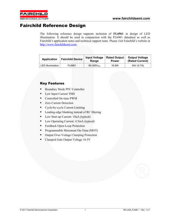
Page 1 Text Content
www.fairchildsemi.com
Fairchild Reference Design
The following reference design supports inclusion of FL6961 in design of LED illumination. It should be used in conjunction with the FL6961 datasheet as well as Fairchild’s application notes and technical support team. Please visit Fairchild’s website at http://www.fairchildsemi.com.
Input Voltage Rated Output Output Voltage
Application Fairchild Device
Range Power (Rated Current)
LED Illumination FL6961 90-265VAC 16.8W 24V (0.7A)
Key Features Boundary Mode PFC Controller Low Input Current THD Controlled On-time PWM Zero Current Detection Cycle-by-cycle Current Limiting Leading-edge blanking instead of RC filtering Low Start-up Current: 10u A (typical) Low Operating Current: 4.5m A (typical) Feedback Open-Loop Protection Programmable Maximum On-Time (MOT) Output Over-Voltage Clamping Protection Clamped Gate Output Voltage 16.5V
© 2011 Fairchild Semiconductor Corporation 1 RD-L009_FL6961 • Rev. 1.0.1
Page Summary Contents For Fairchild RD-009 - FL6961 MOSFET Data Handbook
Manual Details
| Brand | Fairchild |
|---|---|
| Pages | 6 |
| File Size | 256.04 KB |
| Published | June 16, 2026 |
Enter the captcha to get the download link:

Frequently Asked Questions
What input voltage range does the FL6961 reference design support?
It supports an input voltage range of 90-265V AC.
What is the rated output power and current of this LED driver design?
The rated output is 16.8W at 24V and 0.7A.
How can I get the full datasheet and application notes for the FL6961?
Visit Fairchild Semiconductor's website at www.fairchildsemi.com for the datasheet and related resources.