Fairchild RD-LS015 - Fairchild Reference Design FL103M Data Handbook
Summary
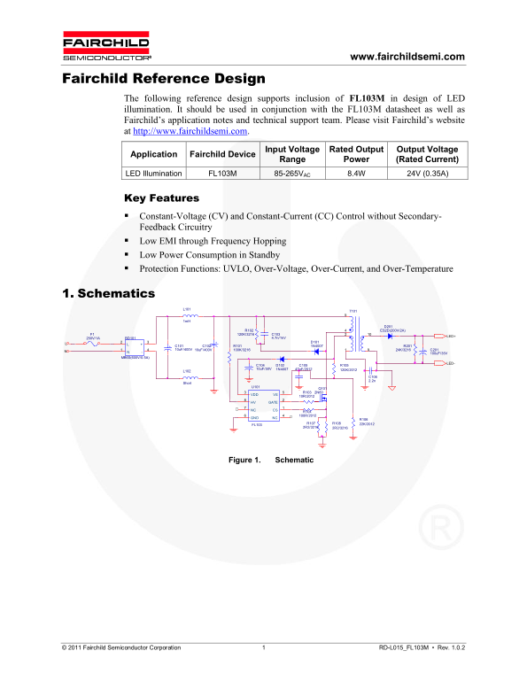
This comprehensive reference design manual details the use of the FL103M driver, engineered for reliable and efficient LED illumination. It provides electrical parameters, layered schematics, transformer winding specifications, and detailed performance curves for both constant voltage (CV) and constant current (CC) control. This resource is essential for electrical engineers and lighting designers building durable, high-performance LED systems that require robust protection features and accurate dimming capabilities.
Page 1 Text Content
www.fairchildsemi.com
Fairchild Reference Design
The following reference design supports inclusion of FL103M in design of LED illumination. It should be used in conjunction with the FL103M datasheet as well as Fairchild’s application notes and technical support team. Please visit Fairchild’s website at http://www.fairchildsemi.com.
Input Voltage Rated Output Output Voltage
Application Fairchild Device
Range Power (Rated Current)
LED Illumination FL103M 85-265VAC 8.4W 24V (0.35A)
Key Features Constant-Voltage (CV) and Constant-Current (CC) Control without Secondary- Feedback Circuitry Low EMI through Frequency Hopping Low Power Consumption in Standby Protection Functions: UVLO, Over-Voltage, Over-Current, and Over-Temperature
1. Schematics
R102 ES2D(200V/2A)
4.7n/1k V LED+
250V/1A BD101
MB6S(600V/0.5A)
Short
VDD VS 10R/2012 HV GATE NC CS R104
GND NC R106
FL103 R107 R108 22K/2012 2R2/3216 2R2/3216
Figure 1. Schematic
© 2011 Fairchild Semiconductor Corporation 1 RD-L015_FL103M • Rev. 1.0.2
Page Summary Contents For Fairchild RD-LS015 - Fairchild Reference Design FL103M Data Handbook
Manual Details
| Brand | Fairchild |
|---|---|
| Pages | 5 |
| File Size | 269.55 KB |
| Published | May 20, 2026 |
Enter the captcha to get the download link:

Frequently Asked Questions
What is the supported input voltage range?
The device supports an input voltage range of 85-265V AC.
Can this unit handle both constant voltage and current?
Yes, it offers Constant-Voltage (CV) and Constant-Current (CC) Control without secondary feedback circuitry.
What types of protective functions are built-in?
It includes protection for UVLO, Over-Voltage, Over-Current, and Over-Temperature.
Where can I find additional support and documentation?
You must use it in conjunction with the FL103M datasheet, application notes, and Fairchild’s technical support team.