Dell U2417H Monitor Teardown Instructions
Summary
Service manual providing detailed disassembly and reassembly procedures for the Dell U2417H monitor. Includes step-by-step instructions for removing the rear cover, stand, base, USB unit, bracket chassis, panel module, middle bezel, and internal components such as the function board, PSU, and main circuit board. Each step specifies screwdriver type, screw sizes, and torque values. For Dell-authorized service technicians performing hardware repair.
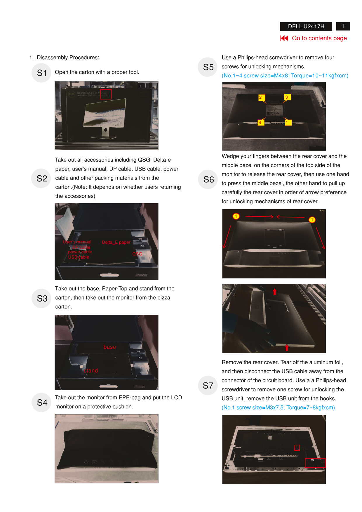
Page 1 Text Content
DELL U2417H
Go to contents page
1. Disassembly Procedures: Use a Philips-head screwdriver to remove four S5 screws for unlocking mechanisms.
Open the carton with a proper tool. S1
(No.1~4 screw size=M4x8; Torque=10~11kgfxcm)
Wedge your fingers between the rear cover and the
Take out all accessories including QSG, Delta-e
middle bezel on the corners of the top side of the
paper, user’s manual, DP cable, USB cable, power
monitor to release the rear cover, then use one hand
S2 cable and other packing materials from the
S6 to press the middle bezel, the other hand to pull up
carton.(Note: It depends on whether users returning
carefully the rear cover in order of arrow preference
the accessories)
for unlocking mechanisms of rear cover.
User’s manual Delta_E paper DP cable power cable
USB cable
Take out the base, Paper-Top and stand from the S3 carton, then take out the monitor from the pizza carton.
Remove the rear cover. Tear off the aluminum foil,
stand and then disconnect the USB cable away from the
connector of the circuit board. Use a a Philips-head S7 screwdriver to remove one screw for unlocking the
Take out the monitor from EPE-bag and put the LCD USB unit, remove the USB unit from the hooks. S4
monitor on a protective cushion. (No.1 screw size=M3x7.5, Torque=7~8kgfxcm)
Page Summary Contents For Dell U2417H Monitor Teardown Instructions
Manual Details
| Brand | Dell |
|---|---|
| Pages | 6 |
| File Size | 6.26 MB |
| Published | June 25, 2026 |
Enter the captcha to get the download link:

Frequently Asked Questions
What tools are required to disassemble the monitor?
Phillips-head screwdrivers #1 and #2, a penknife, and a soldering iron with absorber.
What are the specific torque values for the rear cover screws?
The M4x8 screws for the rear cover require a torque of 10-11 kgf·cm.
Which components require selective disposal according to material information?
Capacitors/condensers, printed circuit boards (surface >10 cm2), and electrolyte capacitors (height >25mm, diameter >25mm).
How do you remove electrolyte capacitors from the PCB?
Cut the glue with a knife, cut into the bottom of the bulk cap, pull it up carefully, and desolder the pins using a soldering iron and absorber.