Dell S3222DGM Monitor Teardown Instructions
Summary
Dell monitor mechanical disassembly instruction providing complete teardown procedures for service and recycling purposes. Documents the step-by-step process: removing the stand-base assembly by pressing the release button, separating the rear cover using a penknife along the bezel edges after removing 4 M4x10 screws, disconnecting internal cables after removing aluminum foil and tape, extracting the latch with 3 D3x6 screws, removing main board and power board with 6 M3x4 screws and 8 additiona
Page 1 Text Content
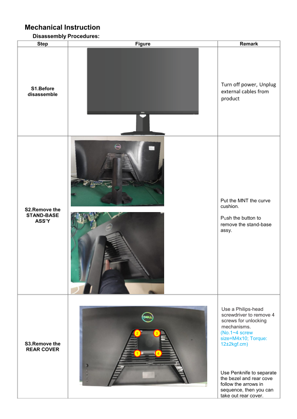
Mechanical Instruction Disassembly Procedures: Step Figure Remark
Turn off power, Unplug
S1.Before
external cables from
disassemble
product
Put the MNT the curve cushion.
S2.Remove the STAND-BASE
Push the button to
ASS’Y
remove the stand-base assy.
Use a Philips-head screwdriver to remove 4 screws for unlocking mechanisms. 2 3 (No.1~4 screw size=M4x10; Torque:
S3.Remove the 12±2kgf.cm) REAR COVER
Use Penknife to separate the bezel and rear cove follow the arrows in sequence, then you can take out rear cover.
Page Summary Contents For Dell S3222DGM Monitor Teardown Instructions
Manual Details
| Brand | Dell |
|---|---|
| Pages | 8 |
| File Size | 1.42 MB |
| Published | May 19, 2026 |
Enter the captcha to get the download link:

Frequently Asked Questions
What is the first step before beginning disassembly?
Before disassembling, you must turn off the power and unplug external cables from the product.
What tools are required for this mechanical disassembly procedure?
The necessary tools include a Phillips-head Screwdriver, Hexagonal Screwdriver, Penknife, and Soldering iron and absorber.
How can I remove the rear cover of the unit?
Use a Philips-head screwdriver to remove 4 screws; also use a penknife to separate the bezel and follow the arrows in sequence.
How must electronic components like PCBs and capacitors be disposed of?
These materials should be disposed of or recovered separately from other WEEE, following Article 4 of EU Council Directive 75/442/EEC.