Dell SE2416HM Monitor Teardown Instructions
Summary
SE2416HM Monitor Disassembly Procedures. Detailed service guide with step-by-step disassembly instructions including stand removal, rear cover separation, mainboard and power board removal, and panel extraction. Includes screw specifications and torque values. Target users: certified monitor repair technicians and service centers.
Page 1 Text Content
SE2416HM 1
1. Disassembly Procedures:
Step Figure Remark
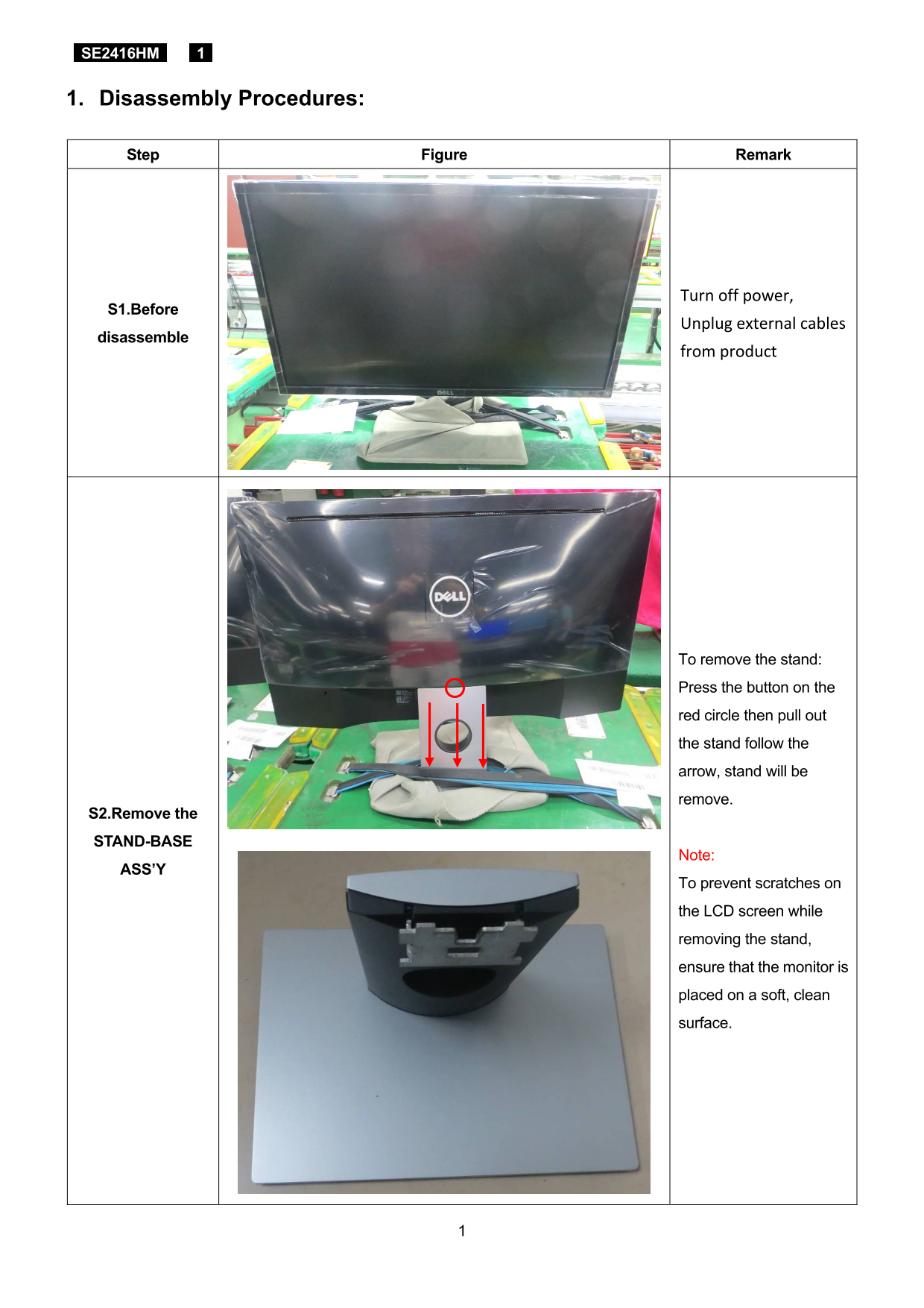
Turn off power,
S1.Before
Unplug external cables
disassemble
from product
To remove the stand: Press the button on the red circle then pull out the stand follow the arrow, stand will be remove.
S2.Remove the STAND-BASE
Note:
ASS’Y
To prevent scratches on the LCD screen while removing the stand, ensure that the monitor is placed on a soft, clean surface.
Page Summary Contents For Dell SE2416HM Monitor Teardown Instructions
Manual Details
| Brand | Dell |
|---|---|
| Pages | 8 |
| File Size | 2.02 MB |
| Published | June 25, 2026 |
Enter the captcha to get the download link:

Frequently Asked Questions
What is required to safely remove the stand?
Press the button on the red circle and then follow the arrow to pull out the stand. Place the monitor on a soft, clean surface first.
Which tools are necessary for disassembly?
You will need a Philips-head screwdriver, Hex screwdriver, Penknife, and a soldering iron and absorber.
How should electronic waste from the product be disposed of?
Disposal must comply with Article 4 of EU Council Directive 75/442/EEC. Specific components like PCBs and capacitors should be handled separately.
What do I need to unscrew the mainboard?
Use a Philips-head screwdriver to remove five screws: four M4x8 (Torque= 6±1kgf.cm) for the board, and one D3x6 screw (Torque= 6±1kgf.cm).