Dell S3422DWG Monitor Teardown Instructions
Summary
This mechanical instruction document provides detailed disassembly procedures for a display monitor. It includes step-by-step instructions with figures for removing the stand base, rear cover, tapes, connectors, latch, main board, power board, panel, middle frame, decorative bezel, USB board, and key board. The manual specifies screw sizes and torque requirements. Intended for repair technicians and service professionals performing monitor hardware maintenance.
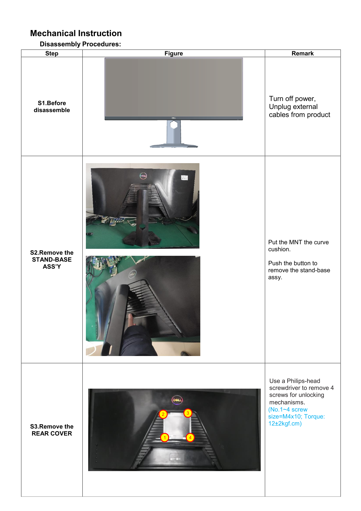
Page 1 Text Content
Mechanical Instruction Disassembly Procedures: Step Figure Remark
Turn off power,
S1.Before
Unplug external
disassemble
cables from product
Put the MNT the curve cushion.
S2.Remove the STAND-BASE
Push the button to
ASS’Y
remove the stand-base assy.
Use a Philips-head screwdriver to remove 4 screws for unlocking mechanisms. (No.1~4 screw
size=M4x10; Torque: 12±2kgf.cm)
S3.Remove the REAR COVER
Page Summary Contents For Dell S3422DWG Monitor Teardown Instructions
Manual Details
| Brand | Dell |
|---|---|
| Pages | 7 |
| File Size | 774.47 KB |
| Published | June 24, 2026 |
Enter the captcha to get the download link:

Frequently Asked Questions
What safety precautions should I take before disassembly?
Turn off the power and unplug all external cables from the product.
What tools are required for disassembly?
A Philips-head screwdriver, hexagonal screwdriver, penknife, and soldering iron with absorber are needed.
How do I remove the rear cover?
Use a penknife to separate the bezel and rear cover following the indicated arrows.
How do I remove large electrolyte capacitors from the PCB?
Remove the big capacitors by lifting them up and away from the PCB after desoldering.