Dell S3222HG Monitor Teardown Instructions
Summary
This comprehensive technical manual provides detailed, step-by-step procedures for the complete mechanical and electrical disassembly of a complex electronic unit. It guides advanced users—such as repair technicians, service engineers, or recycling specialists—through removing major components, including main circuit boards, rear covers, stand bases, and key peripherals. The guide also includes crucial information on tool requirements, component material separation (WEEE compliance), and safe handling practices for electronics recovery and disposal.
Page 1 Text Content
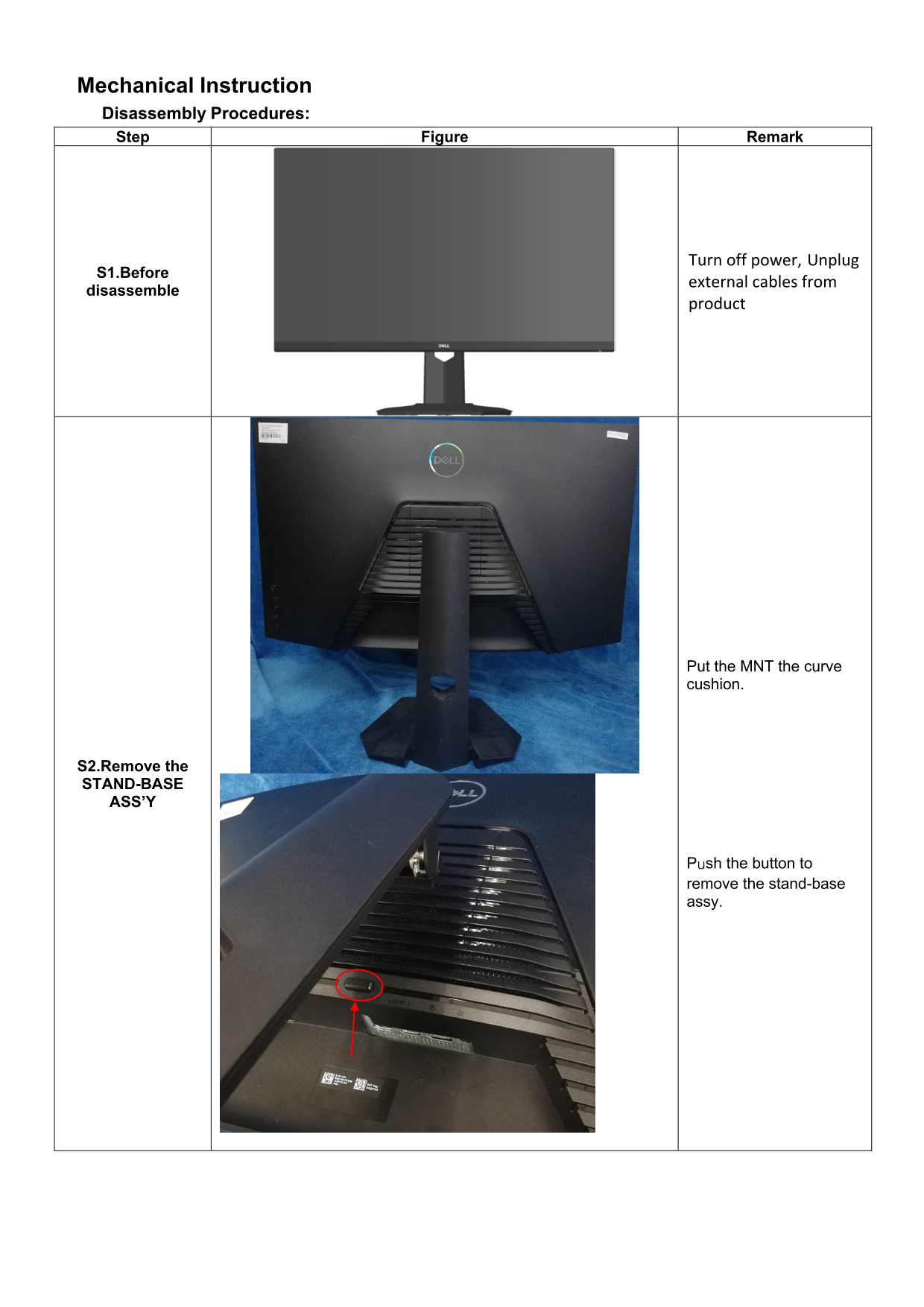
Mechanical Instruction Disassembly Procedures: Step Figure Remark
Turn off power, Unplug
S1.Before
external cables from
disassemble
product
Put the MNT the curve cushion.
S2.Remove the STAND-BASE ASS’Y
Push the button to remove the stand-base assy.
Page Summary Contents For Dell S3222HG Monitor Teardown Instructions
Manual Details
| Brand | Dell |
|---|---|
| Pages | 9 |
| File Size | 1.71 MB |
| Published | June 23, 2026 |
Enter the captcha to get the download link:

Frequently Asked Questions
What is the first step before disassembling the unit?
Turn off the power and unplug all external cables.
Which types of screws are required for various components during disassembly?
The manual lists several screw sizes, including M4x10 (for unlocking mechanisms), D3x6/M3x4 (for main frames), Q2x2.5 (for deco bezels/keyboards), and Latch screws of size D3x6.
How do I remove the rear cover?
Use a penknife to separate the bezel and rear cove, following the arrows in sequence.
What precautions should be taken when disposing of the product or its components?
The user must dispose of capacitors/condensers, printed circuit boards (PCB), and electrolytic capacitors separately according to EU directives.