Dell PowerConnect J- SRX100 Ethernet Switch Quick User Guide
Summary
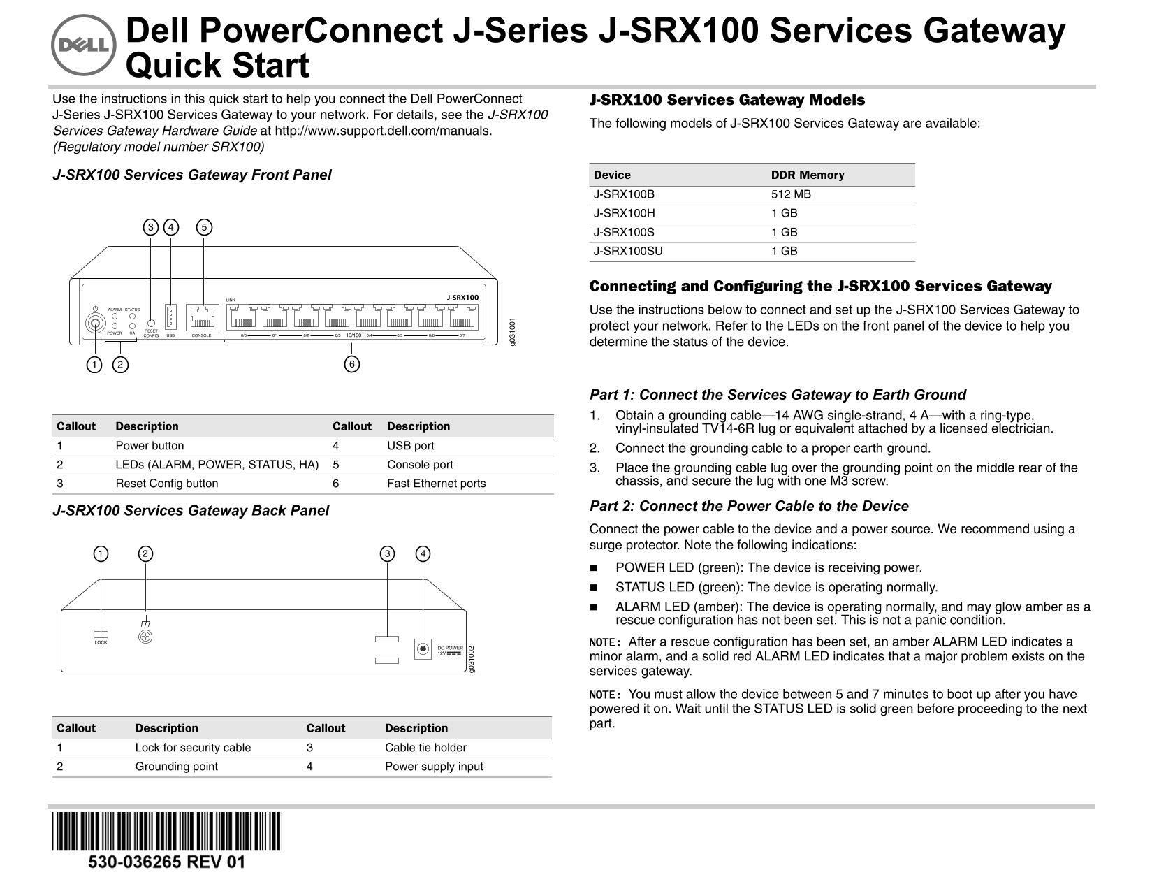
Quick Start guide for the Dell PowerConnect J-Series J-SRX100 Services Gateway (Regulatory model SRX100). Covers front and rear panel overview with LED indicators (ALARM, POWER, STATUS, HA), earth grounding procedures using 14 AWG cable, power cable connection, and initial network configuration. Available in models J-SRX100B (512MB), J-SRX100H (1GB), J-SRX100S (1GB), and J-SRX100SU (1GB).
Page 1 Text Content
Dell Power Connect J-Series J-SRX100 Ser vices Gateway Quick Start Use t he instructions in this quick start to help you connect the Dell Power Connect J-SRX100 Services Gateway M odels J-Ser ies J-SRX100 Services Gateway to your network. For details, see the J-SRX100
The following models of J-SRX100 Ser vices Gateway are available:
Servi ces Gateway Hardware Guide at http://www.support.dell.com/manuals. (Regu latory model number SRX100)
J-SR X100 Services Gateway Front Panel Device DDR Me mory J-SRX100B 512 MB J-SRX100H 1 GB J-SRX100S 1 GB J-SRX100SU 1 GB
Connecting and Configuring t he J-SRX100 Services Gateway
J-SRX100
Use the instructions below to connect a nd set up the J-SRX100 Services Gateway to protect your network. Refer to the LEDs on the front panel of the device to help you determine the status of the device.
Part 1: Connect the Services Gat eway to Earth Ground 1. Obtain a grounding cable—14 AWG single-strand, 4 A—with a ring-type,
Callo ut Description Callout Description vinyl-insulated TV14-6R lug or equ ivalent attached by a licensed electrician.
Power button USB port 2. Connect the grounding cable to a p roper earth ground. LEDs (ALARM, POWER, STATUS, HA) Console port
3. Place the grounding cable lug over the grounding point on the middle rear of the Reset Config button Fast Ethernet ports chassis, and secure the lug with on e M3 screw.
Part 2: Connect the Power Cable to the Device
J-SR X100 Services Gateway Back Panel
Connect the power cable to the device and a power source. We recommend using a surge protector. Note the following indic ations: POWER LED (green): The device is receiving power. STATUS LED (green): The device is operating normally. ALARM LED (amber): The device is operating normally, and may glow amber as a rescue configuration has not been set. This is not a panic condition. NOTE: After a rescue configuration has been set, an amber ALARM LED indicates a minor alarm, and a solid red ALARM LE D indicates that a major problem exists on the services gateway. NOTE: You must allow the device betwe en 5 and 7 minutes to boot up after you have powered it on. Wait until the STATUS L ED is solid green before proceeding to the next part.
Callo ut Description Callout Description
Lock for security cable Cable tie holder Grounding point Power supply input
Page Summary Contents For Dell PowerConnect J- SRX100 Ethernet Switch Quick User Guide
Manual Details
| Brand | Dell |
|---|---|
| Pages | 36 |
| File Size | 3.60 MB |
| Published | July 02, 2026 |
Enter the captcha to get the download link:

Frequently Asked Questions
How long should I wait after powering on the gateway before proceeding with setup?
You must allow the device between 5 and 7 minutes to boot up, waiting until the STATUS LED is solid green before continuing.
What key components do I need when connecting to earth ground?
Use a 14 AWG single-strand, 4 A grounding cable with a ring-type lug attached by a licensed electrician.
Which light indicators signal normal versus critical operational status?
Green STATUS indicates normal operation. Amber ALARM means a minor alarm or no rescue config; solid red ALARM signals a major problem.
How do I connect and assign an IP address to the management device?
Use DHCP by connecting Ethernet from fe-0/0/1 through 7, or use the CONSOLE port with a DB-9 adapter for manual configuration.