Dell PowerConnect J-EX4200-24t Ethernet Switch Quick User Guide
Summary
The Dell PowerConnect J-Series J-EX4200 Ethernet Switch Quick Start Guide covers enterprise switch installation. Models include EX4200-24T, EX4200-24F, and EX4200-48T variants. The guide details rack mounting, grounding, AC/DC power connections, and Virtual Chassis configuration. Target users are network administrators deploying enterprise switching infrastructure.
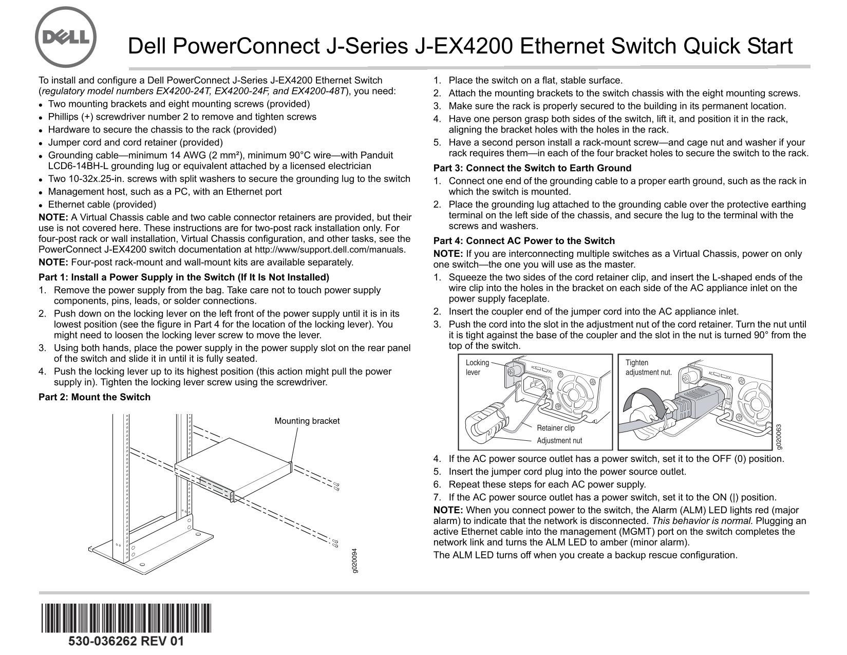
Page 1 Text Content
Dell Power Connect J-Series J-EX4200 Ethernet Switch Quick Start To install and configure a Dell Power Connect J-Series J-EX4200 Ethernet Switch 1. Place the switch on a flat, stable surface.
(regulatory model numbers EX4200-24T, EX4200-24F, and EX4200-48T), you need: 2. Attach the mounting brackets to the switch chassis with the eight mounting screws. Two mounting brackets and eight mounting screws (provided) 3. Make sure the rack is properly secured to the building in its permanent location. Phillips (+) screwdriver number 2 to remove and tighten screws 4. Have one person grasp both sides of the switch, lift it, and position it in the rack,
Hardware to secure the chassis to the rack (provided) aligning the bracket holes with the holes in the rack.
Jumper cord and cord retainer (provided) 5. Have a second person install a rack-mount screw—and cage nut and washer if your
Grounding cable—minimum 14 AWG (2 mm²), minimum 90°C wire—with Panduit rack requires them—in each of the four bracket holes to secure the switch to the rack.
LCD6-14BH-L grounding lug or equivalent attached by a licensed electrician Part 3: Connect the Switch to Earth Ground Two 10-32x.25-in. screws with split washers to secure the grounding lug to the switch 1. Connect one end of the grounding cable to a proper earth ground, such as the rack in Management host, such as a PC, with an Ethernet port which the switch is mounted. Ethernet cable (provided) 2. Place the grounding lug attached to the grounding cable over the protective earthing
NOTE: A Virtual Chassis cable and two cable connector retainers are provided, but their terminal on the left side of the chassis, and secure the lug to the terminal with the use is not covered here. These instructions are for two-post rack installation only. For screws and washers.
four-post rack or wall installation, Virtual Chassis configuration, and other tasks, see the Part 4: Connect AC Power to the Switch Power Connect J-EX4200 switch documentation at http://www/support.dell.com/manuals.
NOTE: If you are interconnecting multiple switches as a Virtual Chassis, power on only
NOTE: Four-post rack-mount and wall-mount kits are available separately. one switch—the one you will use as the master. Part 1: Install a Power Supply in the Switch (If It Is Not Installed) 1. Squeeze the two sides of the cord retainer clip, and insert the L-shaped ends of the
1. Remove the power supply from the bag. Take care not to touch power supply wire clip into the holes in the bracket on each side of the AC appliance inlet on the components, pins, leads, or solder connections. power supply faceplate. 2. Push down on the locking lever on the left front of the power supply until it is in its 2. Insert the coupler end of the jumper cord into the AC appliance inlet.
lowest position (see the figure in Part 4 for the location of the locking lever). You 3. Push the cord into the slot in the adjustment nut of the cord retainer. Turn the nut until might need to loosen the locking lever screw to move the lever. it is tight against the base of the coupler and the slot in the nut is turned 90° from the
3. Using both hands, place the power supply in the power supply slot on the rear panel top of the switch.
of the switch and slide it in until it is fully seated.
Locking Tighten
DC AC
4. Push the locking lever up to its highest position (this action might pull the power lever adjustment nut.
supply in). Tighten the locking lever screw using the screwdriver. Part 2: Mount the Switch
Retainer clip Adjustment nut
4. If the AC power source outlet has a power switch, set it to the OFF (0) position. 5. Insert the jumper cord plug into the power source outlet. 6. Repeat these steps for each AC power supply. 7. If the AC power source outlet has a power switch, set it to the ON (|) position. NOTE: When you connect power to the switch, the Alarm (ALM) LED lights red (major alarm) to indicate that the network is disconnected. This behavior is normal. Plugging an active Ethernet cable into the management (MGMT) port on the switch completes the network link and turns the ALM LED to amber (minor alarm). The ALM LED turns off when you create a backup rescue configuration.
Page Summary Contents For Dell PowerConnect J-EX4200-24t Ethernet Switch Quick User Guide
Manual Details
| Brand | Dell |
|---|---|
| Pages | 24 |
| File Size | 3.17 MB |
| Published | June 25, 2026 |
Enter the captcha to get the download link:

Frequently Asked Questions
How do I install the switch in a rack?
Attach mounting brackets to the chassis, align the holes with the rack, and secure with four screws.
How do I connect the grounding cable?
Connect one end to a proper earth ground, place the lug over the protective terminal on the left side of the chassis, and secure it with screws.
What should I do if the Alarm LED lights red?
This indicates the network is disconnected. Plugging an active Ethernet cable into the management port will complete the link and turn the LED amber.
How do I perform the initial configuration?
Connect an Ethernet cable from port 0 to a PC, access http://192.168.1.1, and complete the EZSetup wizard within 10 minutes.
What are the safety requirements for installation?
Only trained employees should install or replace components. Ensure the rack is properly secured and the installation site meets environmental requirements.