Dell PowerConnect J-8208 Ethernet Switch Quick Start Guide and User Manual
Summary
Quick start guide for the Dell PowerConnect J-Series J-EX8208 Ethernet Switch (regulatory model EX8208). The document provides installation instructions including rack mounting with mechanical lift, grounding procedures, power supply connection, management host setup, and initial configuration through CLI. It covers hardware components such as mounting brackets, power cord tray, grounding cable, and required tools. The guide also includes basic switch configuration commands for network connectivity. Target users are network engineers and data center technicians performing initial deployment of Dell J-Series enterprise Ethernet switches.
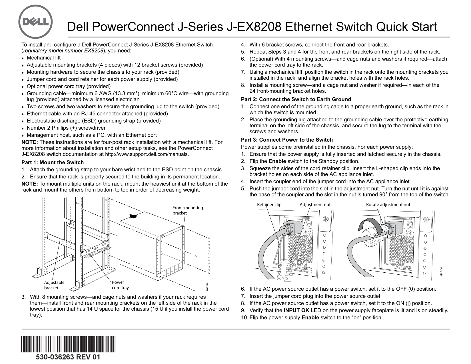
Page 1 Text Content
Dell Power Connect J-Series J-EX8208 Ethernet Switch Quick Start
To install and configure a Dell Power Connect J-Series J-EX8208 Ethernet Switch 4. With 6 bracket screws, connect the front and rear brackets.
(regulatory model number EX8208), you need: 5. Repeat Steps 3 and 4 for the front and rear brackets on the right side of the rack. Mechanical lift 6. (Optional) With 4 mounting screws—and cage nuts and washers if required—attach
Adjustable mounting brackets (4 pieces) with 12 bracket screws (provided) the power cord tray to the rack. Mounting hardware to secure the chassis to your rack (provided) 7. Using a mechanical lift, position the switch in the rack onto the mounting brackets you Jumper cord and cord retainer for each power supply (provided) installed in the rack, and align the bracket holes with the rack holes. Optional power cord tray (provided) 8. Install a mounting screw—and a cage nut and washer if required—in each of the front-mounting bracket holes.
Grounding cable—minimum 6 AWG (13.3 mm²), minimum 60°C wire—with grounding
lug (provided) attached by a licensed electrician Part 2: Connect the Switch to Earth Ground Two screws and two washers to secure the grounding lug to the switch (provided) 1. Connect one end of the grounding cable to a proper earth ground, such as the rack in Ethernet cable with an RJ-45 connector attached (provided) which the switch is mounted. Electrostatic discharge (ESD) grounding strap (provided) 2. Place the grounding lug attached to the grounding cable over the protective earthing terminal on the left side of the chassis, and secure the lug to the terminal with the
Number 2 Phillips (+) screwdriver
screws and washers.
Management host, such as a PC, with an Ethernet port
Part 3: Connect Power to the Switch
NOTE: These instructions are for four-post rack installation with a mechanical lift. For
more information about installation and other setup tasks, see the Power Connect Power supplies come preinstalled in the chassis. For each power supply: J-EX8208 switch documentation at http://www.support.dell.com/manuals. 1. Ensure that the power supply is fully inserted and latched securely in the chassis. Part 1: Mount the Switch 2. Flip the Enable switch to the Standby position. 1. Attach the grounding strap to your bare wrist and to the ESD point on the chassis. 3. Squeeze the sides of the cord retainer clip. Insert the L-shaped clip ends into the bracket holes on each side of the AC appliance inlet.
2. Ensure that the rack is properly secured to the building in its permanent location.
4. Insert the coupler end of the jumper cord into the AC appliance inlet.
NOTE: To mount multiple units on the rack, mount the heaviest unit at the bottom of the
rack and mount the others from bottom to top in order of decreasing weight. 5. Push the jumper cord into the slot in the adjustment nut. Turn the nut until it is against the base of the coupler and the slot in the nut is turned 90° from the top of the switch.
6. If the AC power source outlet has a power switch, set it to the OFF (0) position. 3. With 8 mounting screws—and cage nuts and washers if your rack requires 7. Insert the jumper cord plug into the power source outlet.
them—install front and rear mounting brackets on the left side of the rack in the 8. If the AC power source outlet has a power switch, set it to the ON (|) position. lowest position that has 14 U space for the chassis (15 U if you install the power cord
9. Verify that the INPUT OK LED on the power supply faceplate is lit and is on steadily.
tray).
10. Flip the power supply Enable switch to the “on” position.
Page Summary Contents For Dell PowerConnect J-8208 Ethernet Switch Quick Start Guide and User Manual
Manual Details
| Brand | Dell |
|---|---|
| Pages | 24 |
| File Size | 2.55 MB |
| Published | June 27, 2026 |
Enter the captcha to get the download link:
