Dell P2418HZM Monitor Teardown Instructions
Summary
This comprehensive technical document provides detailed product information, installation guidance, configuration procedures, and operational instructions to ensure optimal product utilization in professional environments. This document provides comprehensive guidance for a Dell display solution. It covers display setup, image adjustment, input management, and advanced display features to optimize visual performance. It is designed for IT professionals and system administrators who need reliable technical documentation for deployment, management, and support of the product.
Page 1 Text Content
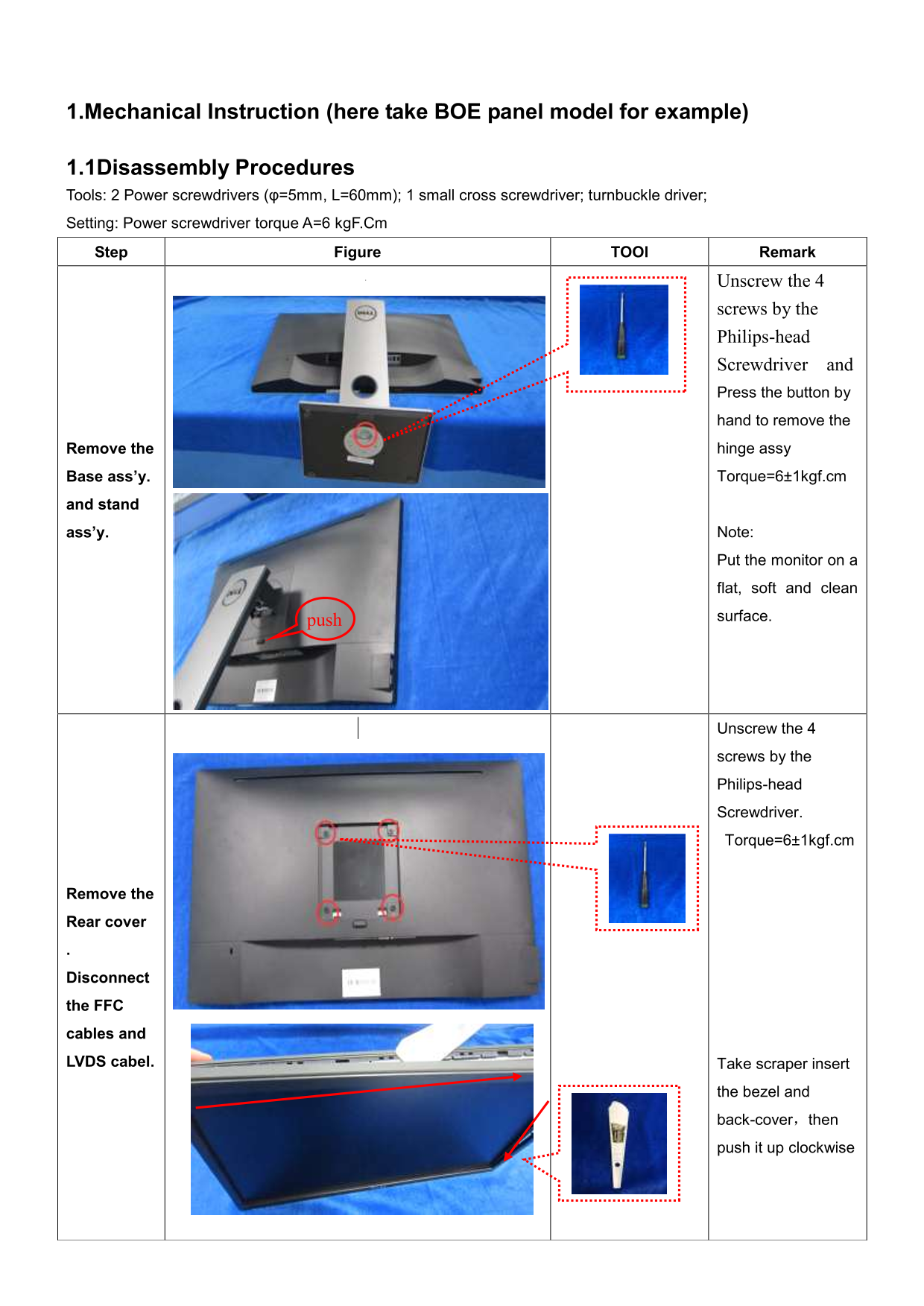
1.Mechanical Instruction (here take BOE panel model for example)
1.1Disassembly Procedures Tools: 2 Power screwdrivers (φ=5mm, L=60mm); 1 small cross screwdriver; turnbuckle driver; Setting: Power screwdriver torque A=6 kg F.Cm Step Figure TOOl Remark
Unscrew the 4
screws by the Philips-head Screwdriver and Press the button by hand to remove the Remove the hinge assy Base ass’y. Torque=6±1kgf.cm
and stand
ass’y. Note:
Put the monitor on a
flat, soft and clean
surface.
Unscrew the 4
screws by the
Philips-head
Screwdriver.
Torque=6±1kgf.cm
Remove the
Rear cover
Disconnect
the FFC
cables and
LVDS cabel. Take scraper insert
the bezel and
back-cover,then push it up clockwise
Page Summary Contents For Dell P2418HZM Monitor Teardown Instructions
Manual Details
| Brand | Dell |
|---|---|
| Pages | 5 |
| File Size | 346.90 KB |
| Published | June 23, 2026 |
Enter the captcha to get the download link:

Frequently Asked Questions
What tools are required for disassembly?
Use 2 power screwdrivers (φ=5mm, L=60mm), a small cross screwdriver, turnbuckle driver, and a penknife.
What is the recommended screwdriver torque setting?
Set the power screwdriver torque to 6 kgF.Cm.
Which materials must be disposed of separately?
Capacitors, PCBs over 10 sq cm, LCDs over 100 cm2, and electrolyte capacitors (diameter/height > 25mm).
How do I remove the rear cover?
Unscrew the screws, disconnect FFC and LVDS cables, then use a scraper to separate the bezel and back cover.