Dell P2417H Monitor Teardown Instructions
Summary
Mechanical instruction document for Dell monitor disassembly and assembly procedures, providing step-by-step guidance with tool specifications and torque requirements. Covers removal of hinge assembly, stand, rear cover, FFC and LVDS cables, mainboard, power board, electrolyte capacitors, and USB board. Includes product material information for WEEE disposal compliance listing capacitors, relays, and other components requiring separate recovery. Designed for Dell manufacturing and service personnel performing monitor repair operations.
Page 1 Text Content
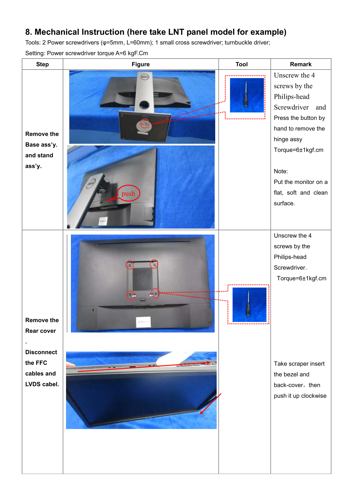
8. Mechanical Instruction (here take LNT panel model for example) Tools: 2 Power screwdrivers (φ=5mm, L=60mm); 1 small cross screwdriver; turnbuckle driver; Setting: Power screwdriver torque A=6 kg F.Cm Step Figure Tool Remark
Unscrew the 4
screws by the Philips-head Screwdriver and Press the button by hand to remove the
Remove the
hinge assy
Base ass’y.
Torque=6±1kgf.cm
and stand
ass’y.
Note:
Put the monitor on a
push flat, soft and clean surface.
Unscrew the 4
screws by the
Philips-head
Screwdriver.
Torque=6±1kgf.cm
Remove the
Rear cover
Disconnect
the FFC Take scraper insert
cables and the bezel and
LVDS cabel. back-cover,then
push it up clockwise
Page Summary Contents For Dell P2417H Monitor Teardown Instructions
Manual Details
| Brand | Dell |
|---|---|
| Pages | 6 |
| File Size | 401.91 KB |
| Published | June 26, 2026 |
Enter the captcha to get the download link:

Frequently Asked Questions
What torque setting should I use for attaching screws?
Use a power screwdriver with a torque setting of 6 kgF.Cm.
Which kind of screwdrivers are needed?
You need Phillips-head, hexagonal head, penknife, and soldering iron/absorber.
How do I remove the monitor's rear cover and cables?
Unscrew four screws (Torque=6±1kgf.cm), disconnect the FFC and LVDS cable, then push up clockwise to remove it.
What specific components should be recycled separately according to WEEE guidelines?
Separate items include capacitors/condensers, printed circuit boards (>10 cm² surface area), batteries, and electrolyte capacitors (height > 25mm).
What specialized tools are required for internal component removal?
Tools include Phillips-head screwdrivers, hexagonal head screwdrivers, a penknife, and soldering iron/absorber.