Dell P2217H Monitor Teardown Instructions
Summary
This document provides detailed mechanical disassembly instructions for a monitor using BOE panel models, including tools required, torque settings, and step-by-step procedures for removing hinge assembly, base/stand assembly, rear cover, FFC/LVDS cables, bezel, mainboard, power board, and panel components. It also includes product material information and WEEE compliance requirements. Target users include manufacturing technicians and service repair professionals performing monitor assembly or disassembly operations.
Page 1 Text Content
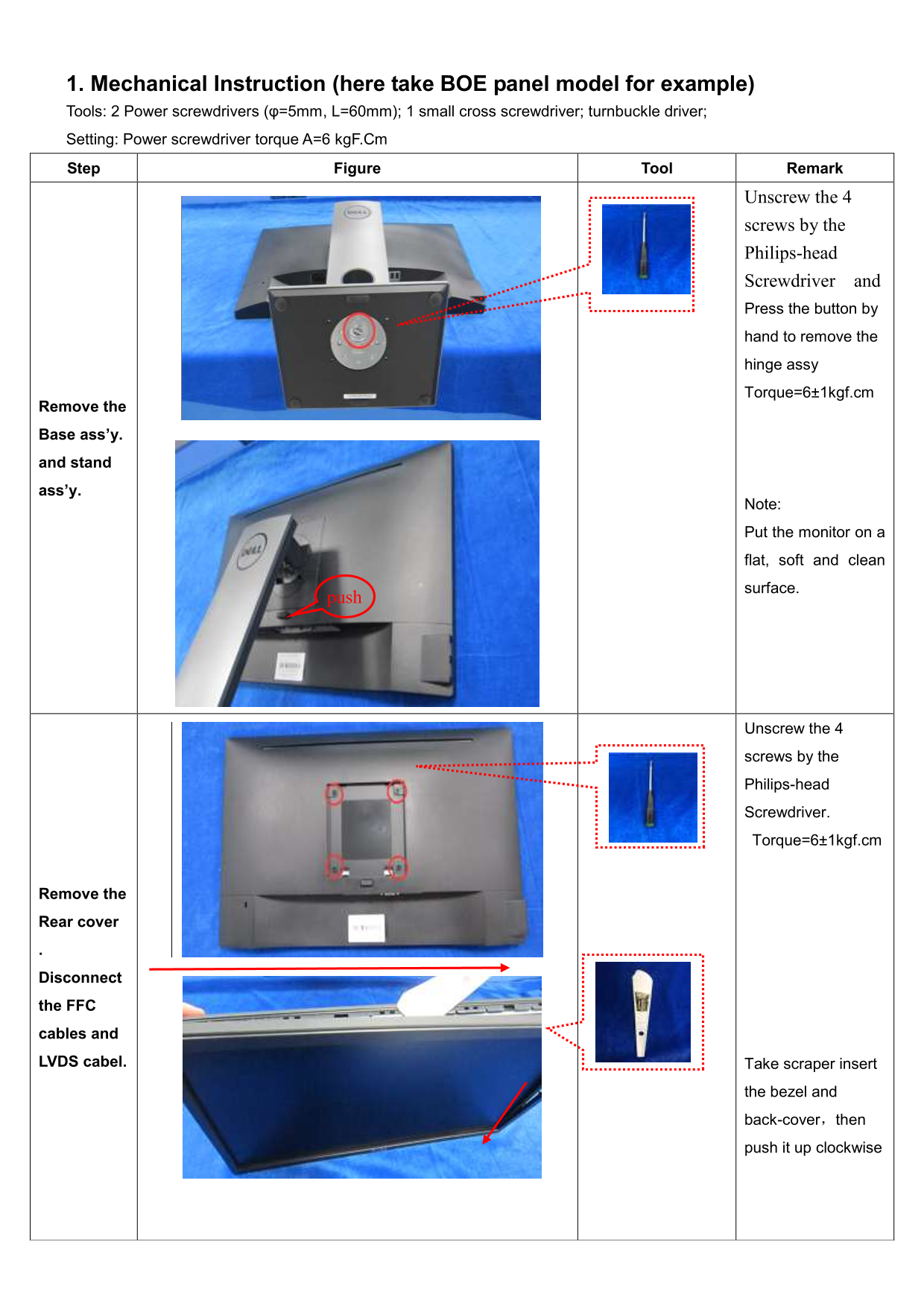
1. Mechanical Instruction (here take BOE panel model for example) Tools: 2 Power screwdrivers (φ=5mm, L=60mm); 1 small cross screwdriver; turnbuckle driver; Setting: Power screwdriver torque A=6 kg F.Cm Step Figure Tool Remark
Unscrew the 4
screws by the Philips-head Screwdriver and Press the button by hand to remove the hinge assy Torque=6±1kgf.cm
Remove the
Base ass’y.
and stand
ass’y.
Note:
Put the monitor on a
flat, soft and clean
surface.
Unscrew the 4
screws by the
Philips-head
Screwdriver.
Torque=6±1kgf.cm
Remove the
Rear cover
Disconnect
the FFC
cables and
LVDS cabel. Take scraper insert
the bezel and
back-cover,then push it up clockwise
Page Summary Contents For Dell P2217H Monitor Teardown Instructions
Manual Details
| Brand | Dell |
|---|---|
| Pages | 6 |
| File Size | 394.89 KB |
| Published | June 24, 2026 |
Enter the captcha to get the download link:

Frequently Asked Questions
What tools are required for disassembly?
Required tools include a φ=5mm, L=60mm power screwdriver, a small Phillips-head screwdriver, a turnbuckle driver, and a soldering iron with an absorber.
What is the required torque for screws?
The required torque for the Phillips-head screws is 6±1kgf.cm.
Where should the monitor be placed during disassembly?
Place the monitor on a flat, soft, and clean surface.
Which components are subject to separate recovery?
Capacitors with a height or diameter >25mm, PCBs with a surface area >10 sq cm, and cables are subject to separate recovery.