Carrier 45J 45J,K,M,N,Q,R Fan Powered Variable Air Volume Terminals
Summary
These fan-powered Variable Air Volume (VAV) terminals are critical components used in HVAC systems for precisely regulating airflow and maintaining optimal environmental conditions. This comprehensive manual provides expert instructions covering complete unit installation, initial start-up procedures, and advanced service guides. It details everything from making duct connections and system calibration with various control inputs (analog, pneumatic) to troubleshooting motor maintenance. It is designed specifically for trained HVAC technicians and facility managers ensuring the safe, efficient, and reliable operation of complex climate control units.
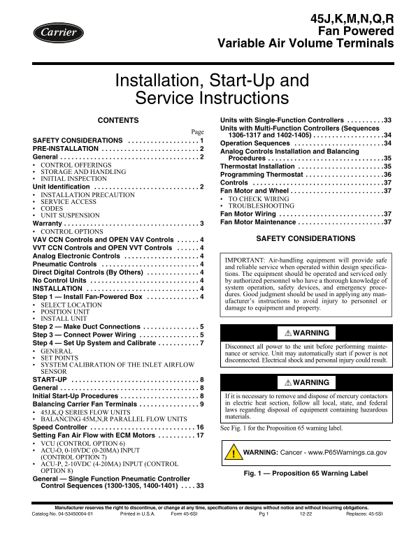
Page 1 Text Content
45J,K,M,N,Q,R Fan Powered
Variable Air Volume Terminals
Installation, Start-Up and Service Instructions
CONTENTS Units with Single-Function Controllers . . . . . . . . . .33 Units with Multi-Function Controllers (Sequences
1306-1317 and 1402-1405) . . . . . . . . . . . . . . . . . . .34
SAFETY CONSIDERATIONS . . . . . . . . . . . . . . . . . . .
Operation Sequences . . . . . . . . . . . . . . . . . . . . . . . .34
PRE-INSTALLATION . . . . . . . . . . . . . . . . . . . . . . . . . .
Analog Controls Installation and Balancing
General . . . . . . . . . . . . . . . . . . . . . . . . . . . . . . . . . . . . . Procedures . . . . . . . . . . . . . . . . . . . . . . . . . . . . . . .35 CONTROL OFFERINGS Thermostat Installation . . . . . . . . . . . . . . . . . . . . . . .35 STORAGE AND HANDLING
Programming Thermostat . . . . . . . . . . . . . . . . . . . . .36
INITIAL INSPECTION
Controls . . . . . . . . . . . . . . . . . . . . . . . . . . . . . . . . . . .37
Unit Identification . . . . . . . . . . . . . . . . . . . . . . . . . . . .
Fan Motor and Wheel . . . . . . . . . . . . . . . . . . . . . . . . .37
INSTALLATION PRECAUTION
TO CHECK WIRING
SERVICE ACCESS
TROUBLESHOOTING
CODES
UNIT SUSPENSION Fan Motor Wiring . . . . . . . . . . . . . . . . . . . . . . . . . . . .37 Warranty . . . . . . . . . . . . . . . . . . . . . . . . . . . . . . . . . . . . Fan Motor Maintenance . . . . . . . . . . . . . . . . . . . . . . .37
CONTROL OPTIONS
VAV CCN Controls and OPEN VAV Controls . . . . . . SAFETY CONSIDERATIONS
VVT CCN Controls and OPEN VVT Controls . . . . . . Analog Electronic Controls . . . . . . . . . . . . . . . . . . . .
IMPORTANT: Air-handling equipment will provide safe
Pneumatic Controls . . . . . . . . . . . . . . . . . . . . . . . . . .
and reliable service when operated within design specifica-
Direct Digital Controls (By Others) . . . . . . . . . . . . . . tions. The equipment should be operated and serviced only No Control Units . . . . . . . . . . . . . . . . . . . . . . . . . . . . . by authorized personnel who have a thorough knowledge of
INSTALLATION . . . . . . . . . . . . . . . . . . . . . . . . . . . . . . system operation, safety devices, and emergency proce- dures. Good judgment should be used in applying any man-
Step 1 — Install Fan-Powered Box . . . . . . . . . . . . . .
ufacturer’s instructions to avoid injury to personnel or
SELECT LOCATION
damage to equipment and property.
POSITION UNIT INSTALL UNIT Step 2 — Make Duct Connections . . . . . . . . . . . . . . .
WARNING
Step 3 — Connect Power Wiring . . . . . . . . . . . . . . . . Step 4 — Set Up System and Calibrate . . . . . . . . . . .
Disconnect all power to the unit before performing mainte-
GENERAL
nance or service. Unit may automatically start if power is not
SET POINTS
disconnected. Electrical shock and personal injury could result.
SYSTEM CALIBRATION OF THE INLET AIRFLOW SENSOR START-UP . . . . . . . . . . . . . . . . . . . . . . . . . . . . . . . . . .
WARNING
General . . . . . . . . . . . . . . . . . . . . . . . . . . . . . . . . . . . . . Initial Start-Up Procedures . . . . . . . . . . . . . . . . . . . . . If it is necessary to remove and dispose of mercury contactors
Balancing Carrier Fan Terminals . . . . . . . . . . . . . . . . in electric heat section, follow all local, state, and federal laws regarding disposal of equipment containing hazardous
45J,K,Q SERIES FLOW UNITS
materials.
BALANCING 45M,N,R PARALLEL FLOW UNITS Speed Controller . . . . . . . . . . . . . . . . . . . . . . . . . . . . See Fig. 1 for the Proposition 65 warning label. Setting Fan Air Flow with ECM Motors . . . . . . . . . . VCU (CONTROL OPTION 6) ACU-O, 0-10VDC (0-20MA) INPUT
WARNING: Cancer - www.P65Warnings.ca.gov
(CONTROL OPTION 7) ACU-P, 2-10VDC (4-20MA) INPUT (CONTROL OPTION 8)
Fig. 1 — Proposition 65 Warning Label
General — Single Function Pneumatic Controller Control Sequences (1300-1305, 1400-1401) . . . .
Manufacturer reserves the right to discontinue, or change at any time, specifications or designs without notice and without incurring obligations.
Catalog No. 04-53450004-01 Printed in U.S.A. Form 45-6SI Pg 1 12-22 Replaces: 45-5SI
Page Summary Contents For Carrier 45J 45J,K,M,N,Q,R Fan Powered Variable Air Volume Terminals
Manual Details
| Brand | Carrier |
|---|---|
| Pages | 40 |
| File Size | 2.38 MB |
| Published | June 05, 2026 |
Enter the captcha to get the download link:

Frequently Asked Questions
What should I do if the fan motor does not run?
Check for free rotation of the blower wheel, remove fan packing, verify unit power, and check proper control signal/pie switch setting.
How do I service a units to prevent electrical shock?
Disconnect all main power before performing maintenance or service; the unit may automatically start if power is not disconnected.
What is required when calibrating the inlet airflow sensor?
The general setup involves connecting the ACU-O (0-10VDC, 0-20mA) or ACU-P (2-10VDC, 4-20mA) input to the unit.
If there is excessive fan noise, what might be wrong?
Ensure that all components are securely attached; overtightening motor mounting screws can cause excessive wear.