# A B C D E F G H I J K L M N O P Q R S T U V W X Y Z

ATMEL AVR Microcontrollers ATmega162 ATmega162V Data Sheet

Summary

The ATmega162 is a highly efficient, low-power 8-bit microcontroller built on the AVR enhanced RISC architecture, perfect for advanced embedded systems and real-time control applications. This technical guide provides detailed specifications of the MCU's extensive features, including multiple timers/counters, dual USART interfaces, programmable I/O (up to 35 lines), and robust Flash/EEPROM memory. It is designed for electrical engineers and system designers requiring reliable performance in resource-constrained, low-power electronic devices.
📄 Preview 📖 Table of Contents Contents PAGE OF 22

Page 1 Text Content

BDTIC www.bdtic.com/ATMEL

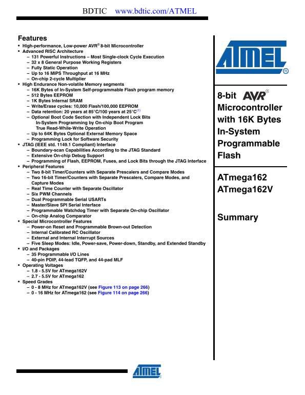
Features High-performance, Low-power AVR® 8-bit Microcontroller Advanced RISC Architecture 131 Powerful Instructions – Most Single-clock Cycle Execution 32 x 8 General Purpose Working Registers Fully Static Operation Up to 16 MIPS Throughput at 16 MHz On-chip 2-cycle Multiplier High Endurance Non-volatile Memory segments 16K Bytes of In-System Self-programmable Flash program memory 512 Bytes EEPROM 8-bit 1K Bytes Internal SRAM Write/Erase cycles: 10,000 Flash/100,000 EEPROM

Microcontroller

Data retention: 20 years at 85°C/100 years at 25°C(1) Optional Boot Code Section with Independent Lock Bits

with 16K Bytes

In-System Programming by On-chip Boot Program True Read-While-Write Operation

Up to 64K Bytes Optional External Memory Space In-System

Programming Lock for Software Security JTAG (IEEE std. 1149.1 Compliant) Interface Programmable Boundary-scan Capabilities According to the JTAG Standard Extensive On-chip Debug Support Flash Programming of Flash, EEPROM, Fuses, and Lock Bits through the JTAG Interface Peripheral Features Two 8-bit Timer/Counters with Separate Prescalers and Compare Modes Two 16-bit Timer/Counters with Separate Prescalers, Compare Modes, and ATmega162 Capture Modes Real Time Counter with Separate Oscillator

ATmega162V

Six PWM Channels Dual Programmable Serial USARTs Master/Slave SPI Serial Interface Programmable Watchdog Timer with Separate On-chip Oscillator On-chip Analog Comparator

Summary

Special Microcontroller Features Power-on Reset and Programmable Brown-out Detection Internal Calibrated RC Oscillator External and Internal Interrupt Sources Five Sleep Modes: Idle, Power-save, Power-down, Standby, and Extended Standby I/O and Packages 35 Programmable I/O Lines 40-pin PDIP, 44-lead TQFP, and 44-pad MLF Operating Voltages 1.8 - 5.5V for ATmega162V 2.7 - 5.5V for ATmega162 Speed Grades 0 - 8 MHz for ATmega162V (see Figure 113 on page 266) 0 - 16 MHz for ATmega162 (see Figure 114 on page 266)

Page Summary Contents For ATMEL AVR Microcontrollers ATmega162 ATmega162V Data Sheet

Page 1 BDTIC www.bdtic.com/ATMEL Features High-performance, Low-power AVR® 8-bit Microcontroller Advanced RISC Architecture 131 Powerful Instructions – Most Single-clock Cycle Execution 32 x 8 General Purpos...
Page 2 Pin Figure 1. Pinout ATmega162 Configurations (OC0/T0) PB0 VCC (OC2/T1) PB1 PA0 (AD0/PCINT0) (RXD1/AIN0) PB2 PA1 (AD1/PCINT1) (TXD1/AIN1) PB3 PA2 (AD2/PCINT2) (SS/OC3B) PB4 PA3 (AD3/PCINT3) (MOSI) PB5...
Page 3 ATmega162/V Overview The ATmega162 is a low-power CMOS 8-bit microcontroller based on the AVR enhanced RISC architecture. By executing powerful instructions in a single clock cycle, the ATmega162 achi...
Page 4 The AVR core combines a rich instruction set with 32 general purpose working registers. All the 32 registers are directly connected to the Arithmetic Logic Unit (ALU), allowing two independent registe...
Page 5 ATmega162/V The timed sequence for changing the Watchdog Time-out period is disabled. See “Timed Sequences for Changing the Configuration of the Watchdog Timer” on page 56 for details. The double buff...
Page 6 Port D (PD7..PD0) Port D is an 8-bit bi-directional I/O port with internal pull-up resistors (selected for each bit). The Port D output buffers have symmetrical drive characteristics with both high si...
Page 7 ATmega162/V Resources A comprehensive set of development tools, application notes and datasheets are available for download on http://www.atmel.com/avr. Note: 1. Data Retention Reliability Qualificati...
Page 8 Register Summary Address Name Bit 7 Bit 6 Bit 5 Bit 4 Bit 3 Bit 2 Bit 1 Bit 0 Page (0x FF) Reserved Reserved (0x9E) Reserved (0x9D) Reserved (0x9C) Reserved (0x9B) Reserved (0x9A) Reserved (0x99) Rese...
Page 9 ATmega162/V Address Name Bit 7 Bit 6 Bit 5 Bit 4 Bit 3 Bit 2 Bit 1 Bit 0 Page (0x60) Reserved 0x3F (0x5F) SREG 0x3E (0x5E) SPH SP15 SP14 SP13 SP12 SP11 SP10 SP9 SP8 0x3D (0x5D) SPL SP7 SP6 SP5 SP4 SP3...
Page 10 Address Name Bit 7 Bit 6 Bit 5 Bit 4 Bit 3 Bit 2 Bit 1 Bit 0 Page 0x01 (0x21) UCSR1B RXCIE1 TXCIE1 UDRIE1 RXEN1 TXEN1 UCSZ12 RXB81 TXB81 0x00 (0x20) UBRR1L USART1 Baud Rate Register Low Byte Notes: 1....
Page 11 ATmega162/V Instruction Set Summary Mnemonics Operands Description Operation Flags #Clocks ARITHMETIC AND LOGIC INSTRUCTIONS ADD Rd, Rr Add two Registers Rd ← Rd + Rr Z,C,N,V,H ADC Rd, Rr Add with Car...
Page 12 Mnemonics Operands Description Operation Flags #Clocks BRIE Branch if Interrupt Enabled if ( I = 1) then PC ← PC + k + 1 None 1/2 BRID Branch if Interrupt Disabled if ( I = 0) then PC ← PC + k + 1 Non...
Page 13 ATmega162/V Mnemonics Operands Description Operation Flags #Clocks CLH Clear Half Carry Flag in SREG H ← 0 H MCU CONTROL INSTRUCTIONS NOP No Operation None SLEEP Sleep (see specific descr. for Sleep f...
Page 14 Ordering Information Speed (MHz) Power Supply Ordering Code Package(1) Operation Range ATmega162V-8AI 44A ATmega162V-8PI 40P6 ATmega162V-8MI 44M1 Industrial ATmega162V-8AU(2) 44A (-40°C to 85°C) ATmeg...
Page 15 ATmega162/V Packaging Information PIN 1 PIN 1 IDENTIFIER COMMON DIMENSIONS (Unit of Measure = mm) SYMBOL MIN NOM MAX NOTE D1 9.90 10.00 10.10 Note 2 Notes: 1. This package conforms to JEDEC reference ...
Page 16 SEATING PLANE COMMON DIMENSIONS (Unit of Measure = mm) 0º ~ 15º REF SYMBOL MIN NOM MAX NOTE A1 0.381 52.070 52.578 Note 2 15.240 15.875 E1 13.462 13.970 Note 2 Notes: 1. This package conforms to JEDEC...
Page 17 ATmega162/V Marked Pin# 1 ID SEATING PLANE TOP VIEW Pin #1 Corner SIDE VIEW Option A Pin #1 Triangle COMMON DIMENSIONS (Unit of Measure = mm) E2 SYMBOL MIN NOM MAX NOTE Option B Pin #1 A 0.80 0.90 1.0...
Page 18 Errata The revision letter in this section refers to the revision of the ATmega162 device. ATmega162, all There are no errata for this revision of ATmega162. However, a proposal for solving problems r...
Page 19 ATmega162/V Datasheet Please note that the referring page numbers in this section are referred to this document. The referring revision in this section are referring to the document revision. Revision...
Page 20 5. Updated “Test Access Port – TAP” on page 197 regarding JTAGEN. 6. Updated description for the JTD bit on page 207. 7. Added note on JTAGEN in Table 99 on page 233. 8. Updated Absolute Maximum Ratin...
Page 21 ATmega162/V Changes from Rev. 1. Changed the Endurance on the Flash to 10,000 Write/Erase Cycles. 2513B-09/02 to Rev. 2513C-09/02 Changes from Rev. 1. Added information for ATmega162U. 2513A-05/02 to ...
Page 22 Headquarters International Atmel Corporation Atmel Asia Atmel Europe Atmel Japan 2325 Orchard Parkway Room 1219 Le Krebs 9F, Tonetsu Shinkawa Bldg. San Jose, CA 95131 Chinachem Golden Plaza 8, Rue Jea...

Manual Details

Brand Atmel
Pages 22
File Size 579.57 KB
Published May 15, 2026
207 views

Enter the captcha to get the download link:

captcha

Frequently Asked Questions

What is the required operating voltage range?

The ATmega162V operates between 1.8 - 5.5V, while the general ATmega162 version requires 2.7 - 5.5V.

How much non-volatile memory does the microcontroller provide?

It features 16K Bytes of In-System Flash program memory, 512 Bytes EEPROM, and 1K Bytes Internal SRAM.

What standard interfaces are available for communication?

It supports two programmable Serial USARTs and a Master/Slave SPI Serial Interface for various data transfers.

What functions does the JTAG interface support?

The JTAG (IEEE std. 1149.1 Compliant) interface allows programming of the Flash, EEPROM, Fuses, and Lock Bits, alongside boundary-scan capabilities.