# A B C D E F G H I J K L M N O P Q R S T U V W X Y Z

ABB Type CM Phase Balance Current Relay Specifications and User Guide

Summary

This comprehensive guide details the ABB cM phase Balance current relay, a critical component for monitoring electrical load balance in multi-phase power systems. The manual serves as a deep resource for professional electricians and automation engineers. It provides detailed instructions on installation—including mounting techniques to switchboard panels and correct grounding procedures—and guides users through optimal setup of trip circuits and indicator switches (AC/DC). Essential coverage areas include wiring diagrams, adjusting pickup settings, and guidelines for maintenance and spare parts management, ensuring reliable monitoring across complex substation automation environments.
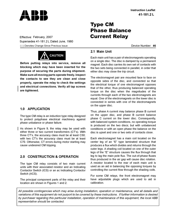
📄 Preview 📖 Table of Contents Contents PAGE OF 12

Page Summary Contents For ABB Type CM Phase Balance Current Relay Specifications and User Guide

Page 2 Il 41-181.2 l c M phase Balance current relay Figure 1 - Non-tapped CM Relay Without Case (Front & Rear Views)
Page 3 c M phase Balance current relay Il 41-181.2 l Front & Rear Views Element Assembly (Front View) Figure 2 - Tapped CM Relay Witthout Case
Page 4 Il 41-181.2 l c M phase Balance current relay The contacts are single-pole, double throw. The Contactor Switch will safely carry this current long moving contact is fastened directly to the disc shaft...
Page 5 c M phase Balance current relay Il 41-181.2 l 6.0 Installat Ion The relays should be mounted on switchboard panels or their equivalent in a location free from dirt, moisture, excessive vibration and h...
Page 6 Il 41-181.2 l c M phase Balance current relay Sub 2 188A146 Figure 4 - Typical Time Curve with Zero Restraint of the Type CM Relay 2. Minimum trip current NOTE: The front electromagnet energized alone...
Page 7 c M phase Balance current relay Il 41-181.2 l 7.2 routine Maintenance used until it is apparent that the relay is not in proper working order. (See “7.1 Acceptance Check”). All relays should be inspec...
Page 8 Il 41-181.2 l c M phase Balance current relay 3. operating curve than the particular ICS tap setting being used. The operation indicator target should drop freely. Apply 6 amperes to front electromagn...
Page 9 c M phase Balance current relay Il 41-181.2 l Sub 1 187A232 Figure 7 - Internal Schematic of Non-Tapped CM Relay, in FT-31 Case Sub 1 762A812 Figure 8 - Internal Schematic of Tapped CM Relay, in FT-31...
Page 10 Il 41-181.2 l c M phase Balance current relay Sub 4 188A144 Figure 9 - External Schematic Diagram for the Type CM Relay in FT-31 Case
Page 11 c M phase Balance current relay Il 41-181.2 l Sub 17 57D7902 Figure 10 - Outline and Drilling Plan for the Type CM Relay in FT-31 Case
Page 12 IL 1- 1. ev . L ABB ABB Inc. 4300 Coral Ridge Drive Coral Springs, Florida 33065 Telephone: +1 954-752-6700 Fax: +1 954-345-5329 www.abb.com/substation automation

Manual Details

Brand Balance
Pages 12
File Size 1.06 MB
Published May 16, 2026
74 views

Enter the captcha to get the download link:

captcha

Frequently Asked Questions

Where should the relay be installed?

Mount it on switchboard panels in a location free from dirt, moisture, excessive vibration, and heat.

How do I physically mount or ground the relay?

Use the rear mounting stud or the four flange holes. Grounding can be achieved via the studs/screws or by connecting ground wires to them.

What dictates the trip circuit closure current when using ACS units?

The moving contact must close with sufficient AC current, which should not exceed the rated operating current of the particular ACS being used.

Can this relay be used for continuous industrial loads?

Yes. The relay may be utilized for continuous load currents from 1 to 7 amperes (for the non-tapped type).

What information is required when ordering renewal parts?

When placing an order, always provide the complete Nameplate data.