# A B C D E F G H I J K L M N O P Q R S T U V W X Y Z

ABB Operating Instruction - FPD470 Wedge Flowmeter Differential Pressure – Primary Flow Element

Summary

The FPD470 Wedge flow meter is a robust differential pressure primary element engineered for precise volumetric flow measurement across diverse industrial applications, suitable for both clean and dirty service conditions. This comprehensive manual provides all necessary operating instructions—from expert installation and start-up procedures to detailed safety precautions, maintenance guidelines, and calibration checks. It is designed for process engineers, facility managers, and technical professionals requiring reliable, calibrated fluid measurement solutions.
📄 Preview 📖 Table of Contents Contents PAGE OF 20

Page 1 Text Content

Operating instruction OI/FPD470–EN Rev. A

FPD470 Wedge flow meter Differential pressure – primary flow element

Measurement made easy

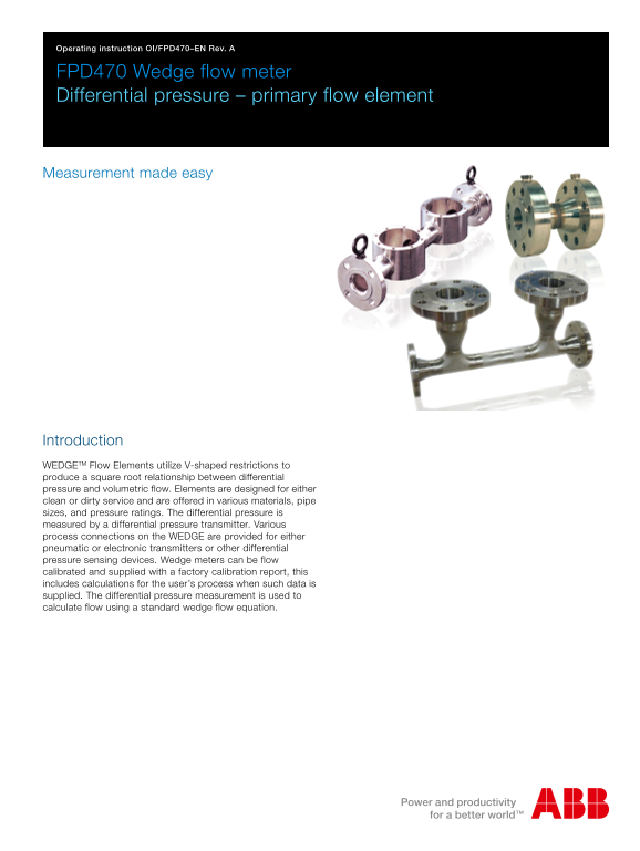
Introduction WEDGETM Flow Elements utilize V-shaped restrictions to produce a square root relationship between differential pressure and volumetric flow. Elements are designed for either clean or dirty service and are offered in various materials, pipe sizes, and pressure ratings. The differential pressure is measured by a differential pressure transmitter. Various process connections on the WEDGE are provided for either pneumatic or electronic transmitters or other differential pressure sensing devices. Wedge meters can be flow calibrated and supplied with a factory calibration report, this includes calculations for the user’s process when such data is supplied. The differential pressure measurement is used to calculate flow using a standard wedge flow equation.

Page Summary Contents For ABB Operating Instruction - FPD470 Wedge Flowmeter Differential Pressure – Primary Flow Element

Page 1 Operating instruction OI/FPD470–EN Rev. A FPD470 Wedge flow meter Differential pressure – primary flow element Measurement made easy Introduction WEDGETM Flow Elements utilize V-shaped restrictions to...
Page 2 Contents Health & Safety ..........................................................3 Start-Up ................................................................... 1.1 Document symbols ................
Page 3 Health & Safety 1.1 Document symbols 1.2 Safety precautions Symbols that appear in this document are explained below: Information in this manual is intended only to assist our customers in the eff...
Page 4 1.3 Pressure equipment safety 1.5 Permissible process media (fluids) Process media may be used only if: DANGER – Serious damage to health / risk to life It can be assured that the physical and chemica...
Page 5 Introduction 2.1 General The WEDGE elements are available with up to six different 2.3 Models FPD470F, FPD470C – dirty service These WEDGE Flow elements are offered in a flanged body standard WEDGE ra...
Page 6 2.4 Accuracy Accuracy in % of flow rate Pipe size Water calibrated in Uncalibrated (in.) WEDGE ratio (H/D) factory flow lab * 1 and 11/2 0.2, 0.3, 0.4, 0.5 + 0.5 % + 5 % 2 and 3 0.2, 0.3, 0.4, 0.5 + 0...
Page 7 Installation 3.1 Selecting a mounting location Horizontal installation is recommended for all WEDGE elements rotated 45° to approximately 90° along the pipe center line as shown in Fig. 3.1. This meth...
Page 8 Recommended Minimum Fittings Upstream Downstream Upstream Downstream 3 Elbows close coupled 15D 5D 15D 3D 2 Elbows close coupled out of plane 10D 5D 10D 3D 2 Elbows close coupled in plane 10D 5D 5D 3D...
Page 9 Final torque values for Model FPD470C chemical-tee connections are: 204 °C (400 °F) maximum temperature Garlock® GYLON® 3500 gasket 15.8 to 16.9 N.m (140 to 150 in.lb) 340 °C (645 °F) maximum temperat...
Page 10 Dimensions and weights 4.1 Series FPD470F with flanged tappings and RFWN end flanges 4.1.1 Sizes 40, 50 and 80 mm (11/2, 2 and 3 in.) Typical flanged process connection Flow direction A ±4.58 mm (±0.1...
Page 11 4.1.2 Sizes 100 to 600 mm (4 to 24 in.) Typical flanged process connection Pipe centreline RF-weldneck direction flange shown A ±6.35 mm (±0.25 in.) D max (ref) mm (in.) Approximate weight kg (lbs.) P...
Page 12 4.2 Series FPD470C with chemical-tee tappings and RFSO end flanges 4.2.1 Sizes 15 to 80 mm (1/2 to 3 in.) Approximate weight kg (lbs.) Pipe size Flange rating mm (in.) A ±3.3 mm (±0.13 in.) B mm (in.)...
Page 13 4.3 Series FPD470C with chemical-tee tappings and RFWN end flanges 4.3.1 Sizes 100 to 600 mm (4 to 24 in.) chemical-tee seal connection Pipe centreline RF-weldneck direction flange shown A ±6.35 mm (±...
Page 14 4.4 Series FPD470P with RFWN end flanges 4.4.1 Sizes 50 to 150 mm (2 to 6 in.) NPT tap size Dim typ. 2 places Pipe A mm (in.) B mm (in.) C mm (in.) NPT tap size (in.) Approximate weight kg size Flange...
Page 15 4.4.2 Sizes 200 to 600 mm (8 to 24 in.) Typical threaded connection Pipe centreline direction RF-weldneck flange shown A ±6.35 mm (±0.25 in.) Approximate weight kg (lbs.) Pipe size Flange rating Flang...
Page 16 Start-Up Maintenance 5.1 Operation 6.1 Removing element from service Before any true zero reading can be taken, it is necessary to establish that the process pipe and flow element are completely DANGE...
Page 17 Spares Ref. Description Part No. Qty. Gasket, chemical-tee: Garlock GYLON 3500: Up to 204 °C (400 °F) 43P1604 Graphite: 204 °C (400 °F) to 340 °C (645 °F) 155S1043 Chemical-tee cap screw 9P2342 Table ...
Page 18 Acknowledgements Garlock is the registered trademark of Garlock, an En Pro Industries family of companies, in the United States and / or other countries. GYLON is a registered trademark of Garlock. OI...
Page 19 Notes FPD470 Wedge flow meter | Differential pressure – primary flow element OI/FPD470–EN Rev. A
Page 20 Contact us Note We reserve the right to make technical changes or Process Automation modify the contents of this document without prior Salterbeck Trading Estate notice. With regard to purchase orders...

Manual Details

Brand Element
Pages 20
File Size 1.04 MB
Published June 03, 2026
57 views

Enter the captcha to get the download link:

captcha

Frequently Asked Questions

How can I determine if the flow measurement is accurate at low rates?

The transmitter may show inherent errors when flow rates fall below 30% of maximum flow (9% of maximum differential pressure).

What steps are required during start-up operation?

You must perform a Zero check and a Span check using the procedures provided in the manual.

Are there different versions available for varying service conditions?

Yes, FPD470P is designed for clean service, while models FPD470F and FPD470C are intended for dirty service.

What preparation steps are needed before installing the flow meter?

It requires selecting an appropriate mounting location and ensuring adequate straight pipe run requirements.