ABB Measurement Enabler With Voltage Sockets E2.2 - E4-2 - E6.2 Manual
Summary
Designed for electrical professionals and engineers, this comprehensive manual details the installation, maintenance, and operational procedures for advanced Measurement Enabler modules (e.g., SACE Emax 2). It provides step-by-step guides on utilizing the Ekip Touch display, detailed wiring diagrams for various internal and external sockets, and critical safety protocols covering power disconnection and earthing in multiple languages. Use this guide for safe commissioning, troubleshooting, and routine servicing of high-capacity circuit breaker switchgear.
Page 1 Text Content
Doc. N.° 1SDH001000R0528 - ECN000099978 - Rev. A
SACE Emax 2
Measurement Enabler/Measurement Enabler with voltage socket - E2.2-E4.2-E6.2
CLICK TO PLAY
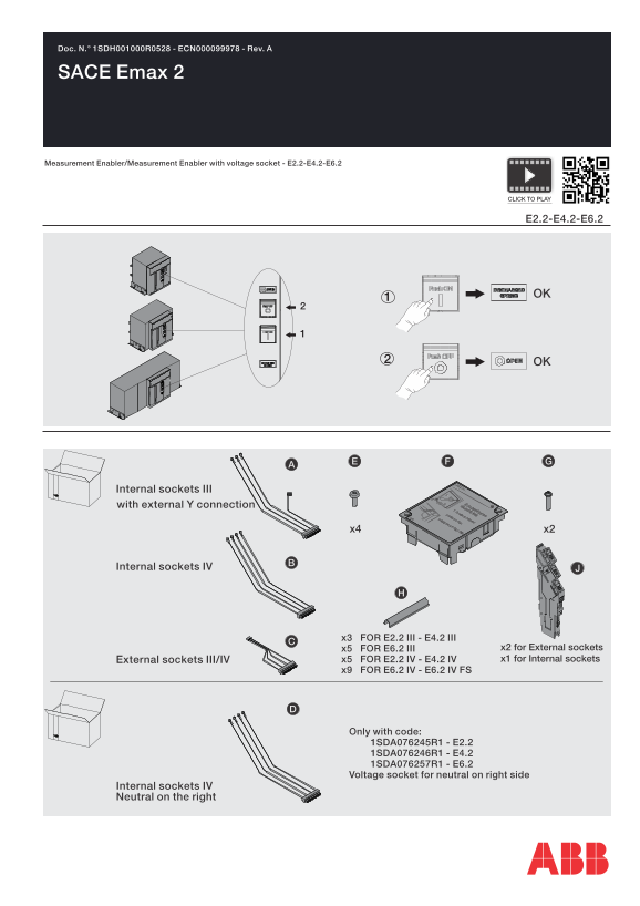
Internal sockets III with external Y connection
Internal sockets IV
x3 FOR E2.2 III - E4.2 III
x5 FOR E6.2 III x2 for External sockets External sockets III/IV x5 FOR E2.2 IV - E4.2 IV x1 for Internal sockets
x9 FOR E6.2 IV - E6.2 IV FS
Only with code: 1SDA076245R1 - E2.2 1SDA076246R1 - E4.2 1SDA076257R1 - E6.2 Voltage socket for neutral on right side
Internal sockets IV Neutral on the right
Page Summary Contents For ABB Measurement Enabler With Voltage Sockets E2.2 - E4-2 - E6.2 Manual
Manual Details
| Brand | Measurement |
|---|---|
| Pages | 20 |
| File Size | 33.19 MB |
| Published | June 03, 2026 |
Enter the captcha to get the download link:

Frequently Asked Questions
What is the correct procedure for installing a Measurement Enabler module?
Insert the Ekip TT E2.2, turn on the unit, wait 10 seconds until the WARNING LED flashes, and then press the INSTALL button on the Ekip Touch display.
If there are alarm icons during installation, where should I refer for assistance?
Consult Manual 1 (or the relevant manual mentioned in local language), as prompted by the procedure.
What information is provided regarding electrical safety when working on fixed circuit breakers?
Disconnection must occur at the power circuit and auxiliary circuits. Terminals must be visibly earthed on both the supply and load sides, adhering to all standards and laws.