ROHM Power driver for CD player BA5961FV Owner's Manual User Guide
Summary
This advanced power driver IC is essential for modern optical disc players, providing robust 1-channel BTL operation for CD, DVD-ROM, and CD-RW units. Featuring integrated operational amplifiers and optimized miniaturization, it ensures reliable tilt coil driving across a variety of demanding applications. This comprehensive manual serves hardware engineers and electro-mechanical system designers, offering detailed electrical characteristics, pin diagrams, operating voltage ranges (PreVCC/PowVCC), and technical guidelines necessary for accurate integration and optimal performance in playback systems.
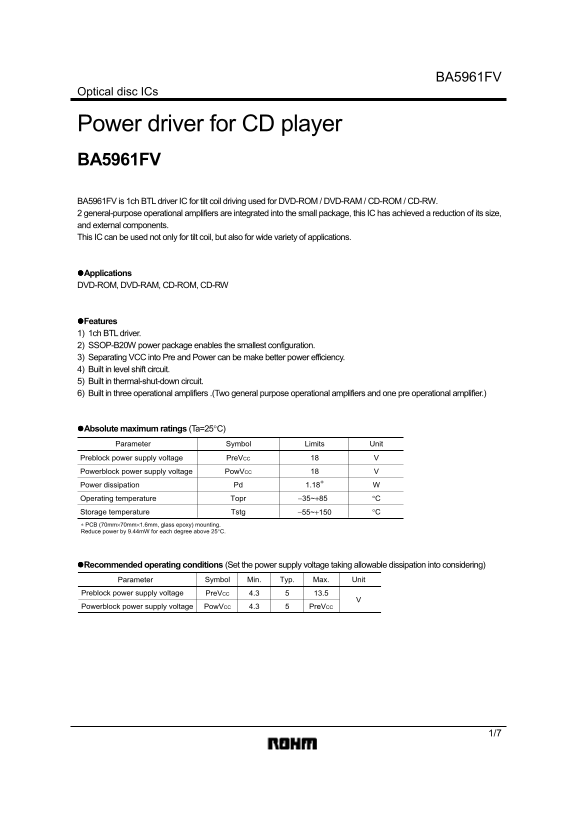
Page 1 Text Content
BA5961FV
Optical disc ICs
Power driver for CD player BA5961FV BA5961FV is 1ch BTL driver IC for tilt coil driving used for DVD-ROM / DVD-RAM / CD-ROM / CD-RW. 2 general-purpose operational amplifiers are integrated into the small package, this IC has achieved a reduction of its size, and external components. This IC can be used not only for tilt coil, but also for wide variety of applications.
!Applications DVD-ROM, DVD-RAM, CD-ROM, CD-RW
!Features 1) 1ch BTL driver. 2) SSOP-B20W power package enables the smallest configuration. 3) Separating VCC into Pre and Power can be make better power efficiency. 4) Built in level shift circuit. 5) Built in thermal-shut-down circuit. 6) Built in three operational amplifiers .(Two general purpose operational amplifiers and one pre operational amplifier.)
!Absolute maximum ratings (Ta=25°C)
Parameter Symbol Limits Unit
Preblock power supply voltage Pre VCC
Powerblock power supply voltage Pow VCC
Power dissipation Pd 1.18∗ Operating temperature Topr −35~+85 °C
Storage temperature Tstg −55~+150 °C
∗ PCB (70mm×70mm×1.6mm, glass epoxy) mounting. Reduce power by 9.44m W for each degree above 25°C.
!Recommended operating conditions (Set the power supply voltage taking allowable dissipation into considering)
Parameter Symbol Min. Typ. Max. Unit
Preblock power supply voltage Pre VCC 4.3 13.5 Powerblock power supply voltage 4.3 Pre VCCPow VCC
Page Summary Contents For ROHM Power driver for CD player BA5961FV Owner's Manual User Guide
Manual Details
| Brand | ROHM |
|---|---|
| Pages | 7 |
| File Size | 96.10 KB |
| Published | May 27, 2026 |
Enter the captcha to get the download link:

Frequently Asked Questions
What materials are required for mounting the IC?
Mounting requires a PCB of glass epoxy material (70mm×70mm×1.6mm).
How is power efficiency affected by ambient temperature?
PreVCC should be kept at least 4.3 V, and PowVCC should meet a minimum of 4.3 V.
How do I prevent oscillation when connecting capacitive loads to the amplifier output?
Insert a series resistance between the output and capacitance load, considering frequency characteristics.