Philips TopFET High Side Switch BUK224-50Y Data Sheet User Manual
Summary
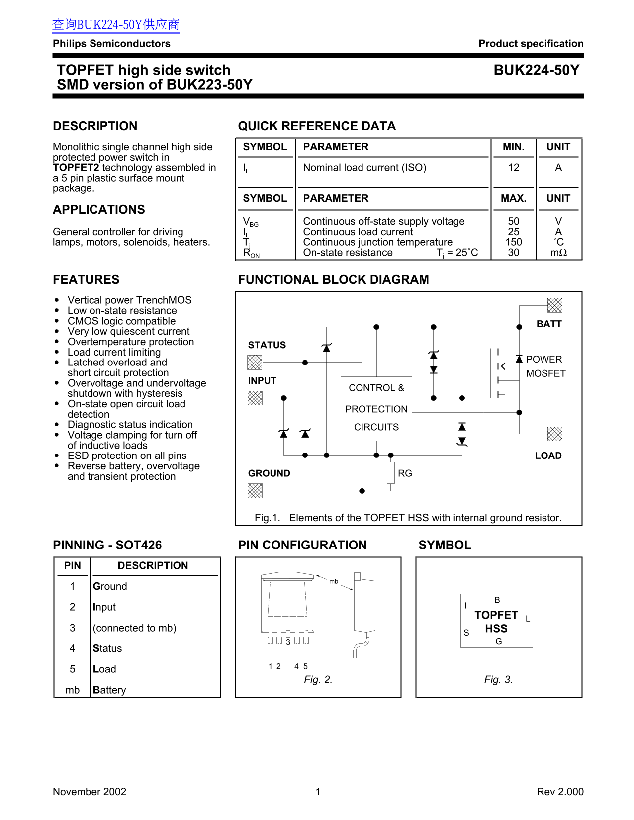
The BUK224-50Y is a miniaturized, high-side protected power switch utilizing advanced TOPFET technology for robust circuit control. This comprehensive manual provides detailed electrical and thermal specifications crucial for system design, covering operational limits up to 50V and continuous load currents of 25A. It is essential documentation for electronics engineers who are developing reliable embedded applications requiring precise switching of inductive loads such as motors, lamps, or solenoids.
Page 1 Text Content
查询BUK224-50Y供应商 Philips Semiconductors Product specification
TOPFET high side switch BUK224-50Y SMD version of BUK223-50Y
DESCRIPTION QUICK REFERENCE DATA Monolithic single channel high side SYMBOL PARAMETER MIN. UNIT protected power switch in
TOPFET2 technology assembled in IL Nominal load current (ISO)
a 5 pin plastic surface mount package.
SYMBOL PARAMETER MAX. UNIT
APPLICATIONS
VBG Continuous off-state supply voltage
General controller for driving IL Continuous load current
lamps, motors, solenoids, heaters. Tj Continuous junction temperature ˚C
RON On-state resistance Tj = 25˚C mΩ
FEATURES FUNCTIONAL BLOCK DIAGRAM Vertical power Trench MOS Low on-state resistance CMOS logic compatible
Very low quiescent current Overtemperature protection
STATUS
Load current limiting
POWER
Latched overload and short circuit protection MOSFET
INPUT
Overvoltage and undervoltage
CONTROL &
shutdown with hysteresis On-state open circuit load
PROTECTION
detection Diagnostic status indication
CIRCUITS
Voltage clamping for turn off of inductive loads
ESD protection on all pins LOAD
Reverse battery, overvoltage
GROUND RG
and transient protection
Fig.1. Elements of the TOPFET HSS with internal ground resistor.
PINNING - SOT426 PIN CONFIGURATION SYMBOL PIN DESCRIPTION
Ground Input
TOPFET
(connected to mb) HSS Status Load
Fig. 2. Fig. 3.
mb Battery
November 2002 Rev 2.000
Page Summary Contents For Philips TopFET High Side Switch BUK224-50Y Data Sheet User Manual
Manual Details
| Brand | Philips |
|---|---|
| Pages | 8 |
| File Size | 44.18 KB |
| Published | July 06, 2026 |
Enter the captcha to get the download link:

Frequently Asked Questions
What is the nominal continuous load current capacity?
The nominal load current (I_L) is 12 A.
How does the device protect against electrical faults?
It features latched overload and short circuit protection, as well as internal overvoltage and undervoltage control/shutdown with hysteresis.
What safety precautions apply to its use?
The product must not be used in life support appliances or systems where malfunction could result in personal injury.
Can the device handle inductive loads?
Yes, it is designed for lamps, motors, solenoids, and heaters, which are common inductive loads.