# A B C D E F G H I J K L M N O P Q R S T U V W X Y Z

National LM117 LM317A LM317 User Guide

Summary

These adjustable voltage regulators (LM117/LM317 series) are essential components for electronics designers requiring highly stable 3-terminal positive power supplies ranging from 1.2V to 25V. Built into this technical guide is everything needed for integration, including detailed electrical specifications, various physical packages (TO-220, SOT), and comprehensive ordering details suitable for high-current applications. Ideal for engineers designing precision circuits needing superior line/load regulation and built-in overload protection.
📄 Preview PAGE OF 26

Page 1 Text Content

/L /L -T rm in l A ju ta le la to

April 2007

LM117/LM317A/LM317 3-Terminal Adjustable Regulator

the maximum input to output differential is not exceeded, i.e.,

General Description

avoid short-circuiting the output.

The LM117 series of adjustable 3-terminal positive voltage

Also, it makes an especially simple adjustable switching reg-

regulators is capable of supplying in excess of 1.5A over a

ulator, a programmable output regulator, or by connecting a

1.2V to 37V output range. They are exceptionally easy to use

fixed resistor between the adjustment pin and output, the

and require only two external resistors to set the output volt-

LM117 can be used as a precision current regulator. Supplies

age. Further, both line and load regulation are better than

with electronic shutdown can be achieved by clamping the

standard fixed regulators. Also, the LM117 is packaged in

adjustment terminal to ground which programs the output to

standard transistor packages which are easily mounted and

1.2V where most loads draw little current.

handled.

For applications requiring greater output current, see LM150

In addition to higher performance than fixed regulators, the

series (3A) and LM138 series (5A) data sheets. For the neg-

LM117 series offers full overload protection available only in

ative complement, see LM137 series data sheet.

IC's. Included on the chip are current limit, thermal overload protection and safe area protection. All overload protection

Features

circuitry remains fully functional even if the adjustment termi-

nal is disconnected. Guaranteed 1% output voltage tolerance (LM317A) Normally, no capacitors are needed unless the device is sit- Guaranteed max. 0.01%/V line regulation (LM317A)

uated more than 6 inches from the input filter capacitors in Guaranteed max. 0.3% load regulation (LM117) which case an input bypass is needed. An optional output ca-

Guaranteed 1.5A output current

pacitor can be added to improve transient response. The

Adjustable output down to 1.2V

adjustment terminal can be bypassed to achieve very high

ripple rejection ratios which are difficult to achieve with stan- Current limit constant with temperature

dard 3-terminal regulators. P+ Product Enhancement tested Besides replacing fixed regulators, the LM117 is useful in a 80 d B ripple rejection wide variety of other applications. Since the regulator is “float-

Output is short-circuit protected

ing” and sees only the input-to-output differential voltage, supplies of several hundred volts can be regulated as long as

LM117/LM317A/LM317 Package Options

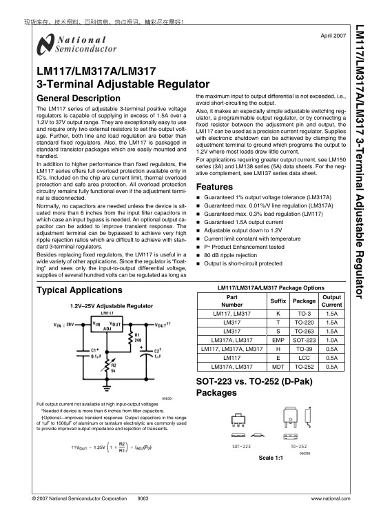
Typical Applications

Part Output

Suffix Package

1.2V–25V Adjustable Regulator Number Current LM117, LM317 TO-3 1.5A LM317 TO-220 1.5A LM317 TO-263 1.5A LM317A, LM317 EMP SOT-223 1.0A LM117, LM317A, LM317 TO-39 0.5A LM117 LCC 0.5A LM317A, LM317 MDT TO-252 0.5A

SOT-223 vs. TO-252 (D-Pak) Packages

Full output current not available at high input-output voltages *Needed if device is more than 6 inches from filter capacitors. †Optional—improves transient response. Output capacitors in the range of 1μF to 1000μF of aluminum or tantalum electrolytic are commonly used to provide improved output impedance and rejection of transients.

Scale 1:1

© 2007 National Semiconductor Corporation www.national.com

Page Summary Contents For National LM117 LM317A LM317 User Guide

Page 1 /L /L -T rm in l A ju ta le la to April 2007 LM117/LM317A/LM317 3-Terminal Adjustable Regulator the maximum input to output differential is not exceeded, i.e., General Description avoid short-circuiti...
Page 2 Connection Diagrams TO-3 (K) TO-39 (H) Metal Can Package Metal Can Package CASE IS OUTPUT Bottom View NS Package Number H03A CASE IS OUTPUT Bottom View Steel Package NS Package Number K02A or K02C TO-...
Page 3 4-Lead SOT-223 (EMP) TO-252 (MDT) Front View NS Package Number MP04A Front View NS Package Number TD03B Ordering Information Temperature Output Order Package Transport NSC Package Range Current Number...
Page 4 Absolute Maximum Ratings (Note 1) Operating Temperature Range If Military/Aerospace specified devices are required, LM117 −55°C ≤ TJ ≤ +150°C please contact the National Semiconductor Sales Office/ LM...
Page 5 /L /L LM317A and LM317 Electrical Characteristics (Note 3) Specifications with standard type face are for TJ = 25°C, and those with boldface type apply over full Operating Temperature Range. Unless ot...
Page 6 Typical Performance Characteristics Output Capacitor = 0 μF unless otherwise noted Load Regulation Current Limit Adjustment Current Dropout Voltage Temperature Stability Minimum Operating Current www....
Page 7 Ripple Rejection Ripple Rejection Ripple Rejection Output Impedance Line Transient Response Load Transient Response www.national.com
Page 8 aluminum electrolytic) on the output swamps this effect and /L /L Application Hints insures stability. Any increase of the load capacitance larger In operation, the LM117 develops a nominal 1.25V refe...
Page 9 diodes included for use with outputs greater than 25V and /L /L high values of output capacitance. FIGURE 4. Power Dissipation Diagram If the calculated maximum allowable thermal resistance is higher ...
Page 10 FIGURE 5. θ(J−A) vs Copper (2 ounce) Area for the FIGURE 7. θ(J−A) vs Copper (1 ounce) Area for the TO-263 SOT-223 Package Package As a design aid, Figure 8 shows the maximum allowable pow- er dissipa...
Page 11 TABLE 1. θJA Different Heatsink Area Layout Copper Area Thermal Resistance Top Side (in2)* Bottom Side (in2) (θJA°C/W) TO-252 Note: * Tab of device attached to topside of copper. FIGURE 9. θJA vs 2oz ...
Page 12 FIGURE 10. Maximum Allowable Power Dissipation vs. Ambient Temperature for TO-252 FIGURE 11. Maximum Allowable Power Dissipation vs. 2oz Copper Area for TO-252 www.national.com
Page 13 FIGURE 12. Top View of the Thermal Test Pattern in Actual Scale www.national.com
Page 14 FIGURE 13. Bottom View of the Thermal Test Pattern in Actual Scale Schematic Diagram www.national.com
Page 15 /L /L †Solid tantalum Typical Applications *Discharges C1 if output is shorted to ground High Stability 10V Regulator 5V Logic Regulator with Electronic Shutdown* *Min. output ≊ 1.2V Slow Turn-On 15V ...
Page 16 High Current Adjustable Regulator ‡Optional—improves ripple rejection †Solid tantalum *Minimum load current = 30 m A 0 to 30V Regulator Power Follower Full output current not available at high input-o...
Page 17 5A Constant Voltage/Constant Current Regulator †Solid tantalum *Lights in constant current mode 1A Current Regulator *Minimum load current ≊ 4 m A High Gain Amplifier 1.2V–20V Regulator with Minimum P...
Page 18 Low Cost 3A Switching Regulator †Solid tantalum *Core—Arnold A-254168-2 60 turns 4A Switching Regulator with Overload Protection †Solid tantalum *Core—Arnold A-254168-2 60 turns Precision Current Limi...
Page 19 /L /L Tracking Preregulator Current Limited Voltage Regulator (Compared to LM117's higher current limit) —At 50 m A output only ¾ volt of drop occurs in R3 and R4 Adjusting Multiple On-Card Regulators...
Page 20 AC Voltage Regulator /L /L 12V Battery Charger Use of RS allows low charging rates with fully charged battery. 50m A Constant Current Battery Charger www.national.com
Page 21 /L /L Adjustable 4A Regulator Current Limited 6V Charger Digitally Selected Outputs *Sets peak current (0.6A for 1Ω) *Sets maximum VOUT **The 1000μF is recommended to filter out input transients www.n...
Page 22 Physical Dimensions inches (millimeters) unless otherwise noted TO-3 Metal Can Package (K) NS Package Number K02A TO-3 Metal Can Package (K) Mil-Aero Product NS Package Number K02C www.national.com
Page 23 TO-39 Metal Can Package (H) NS Package Number H03A 3-Lead TO-220 (T) NS Package Number T03B www.national.com
Page 24 3-Lead TO-263 (S) NS Package Number TS3B Ceramic Leadless Chip Carrier (E) NS Package Number E20A www.national.com
Page 25 4-Lead SOT-223 (EMP) NS Package Number MP04A 3-Lead D-Pack (MDT) NS Package Number TD03B www.national.com
Page 26 /L /L -T rm in ju ta le la to Notes THE CONTENTS OF THIS DOCUMENT ARE PROVIDED IN CONNECTION WITH NATIONAL SEMICONDUCTOR CORPORATION (“NATIONAL”) PRODUCTS. NATIONAL MAKES NO REPRESENTATIONS OR WARRANT...

Manual Details

Brand National
Pages 26
File Size 920.37 KB
Published May 27, 2026
105 views

Enter the captcha to get the download link:

captcha

Frequently Asked Questions

What protection features are included on the regulator chip?

It includes current limit, thermal overload protection, and safe area protection.

Can I use this regulator in high-voltage input scenarios?

Yes, it is 'float-ing' and only sees the input-to-output differential voltage, allowing for voltages of several hundred volts.

Are capacitors required to operate the device?

Normally, no capacitors are needed unless the device is placed more than 6 inches from the input filter capacitors.