# A B C D E F G H I J K L M N O P Q R S T U V W X Y Z

MAXIM MAX9850 Stereo Audio DAC with DirectDrive Headphone Amplifier Data Sheet User Manual

Summary

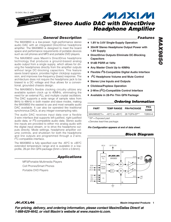
This low-power, high-performance audio DAC integrates a DirectDrive headphone amplifier, making it ideal for portable multimedia devices such as smartphones and MP3 players. Operating on a single 1.8V to 3.6V supply, the MAX9850 delivers stereo audio while eliminating bulky DC-blocking capacitors. The device supports I2S communication and features clickless/popless operation, simplifying board design and improving bass response. This summary guides users through its comprehensive technical capabilities for reliable digital audio conversion in space-constrained applications.
📄 Preview PAGE OF 36

Page 1 Text Content

19-3454; Rev 3; 4/06

EVALUATION KIT AVAILABLE

Stereo Audio DAC with Direct Drive

Headphone Amplifier

General Description Features

The MAX9850 is a low-power, high-performance stereo 1.8V to 3.6V Single-Supply Operation audio DAC with an integrated Direct Drive headphone

30m W Stereo Headphone Output Power with

amplifier. The MAX9850 is designed to meet the board

space and performance requirements of portable devices 1.8V Supply

such as cell phones and MP3 and portable DVD players.

Direct Drive Outputs Eliminate DC-Blocking

The MAX9850 uses Maxim’s Direct Drive headphone Capacitors technology that produces a ground-biased analog

91d B PSRR at 1k Hz

audio output from a single supply, which allows for dri- ving the headphones directly from the amplifier outputs Any Master Clock Up to 40MHz without large DC-blocking capacitors. This feature

Flexible I2S-Compatible Digital Audio Interface

saves board space, provides higher click/pop suppres- sion, and improves low-frequency (bass) response. The I2C Headphone Volume and Mute Control architecture does not require the headphone jack to be

Stereo Line Inputs and Outputs

biased to a DC voltage and thus allows for a conven- tional, grounded chassis design. Clickless/Popless Operation The MAX9850’s flexible clocking circuitry utilizes any

2-Wire (I2C)-Compatible Control Interface

available system clock up to 40MHz, eliminating the

need for an external PLL and multiple crystal oscillators. Available in 28-Pin Thin QFN Package

The DAC supports a wide range of sample rates from 8k Hz to 48k Hz in both master and slave modes, making Ordering Information the MAX9850 the easiest to use and most versatile audio

DAC available. It can also be operated like traditional

PART TEMP RANGE PIN-PACKAGE

synchronous DACs, at any integer-oversampling ratio.

The audio DAC receives input data over a flexible MAX9850ETI+ -40°C to +85°C 28 TQFN-EP** T2855-6

3-wire interface that supports left-justified, right-justified **EP = Exposed pad. audio data, or I2S-compatible audio data. Stereo audio

+Denotes lead-free package.

line inputs are provided to either mix analog audio with the digital input stream, or to drive the headphone out- Pin Configuration appears at end of data sheet. puts directly. Mode settings, headphone amplifier vol- ume controls, and shutdown for both the headphone

Block Diagram

and line outputs are programmed through a 2-wire, I2C-compatible interface. The MAX9850 is fully specified over the -40°C to +85°C

1.8V TO 3.6VMCLK

extended temperature range and is available in a low- profile, 28-pin thin QFN package (5mm x 5mm x 0.8mm).

Applications DIGITAL OUTR LINE

PLL MAX9850 OUT

MP3/Portable Multimedia Players

Cell Phones/Smart Phones DIGITAL

AUDIO

LRCLK HPL

Portable DVD Players +DAC

OUTL LINE

I2C OUT

ADD GPIO

Maxim Integrated Products

For pricing, delivery, and ordering information, please contact Maxim/Dallas Direct! at 1-888-629-4642, or visit Maxim’s website at www.maxim-ic.com.

Page Summary Contents For MAXIM MAX9850 Stereo Audio DAC with DirectDrive Headphone Amplifier Data Sheet User Manual

Page 1 19-3454; Rev 3; 4/06 EVALUATION KIT AVAILABLE Stereo Audio DAC with Direct Drive Headphone Amplifier General Description Features The MAX9850 is a low-power, high-performance stereo 1.8V to 3.6V Singl...
Page 2 Stereo Audio DAC with Direct Drive Headphone Amplifier ABSOLUTE MAXIMUM RATINGS (Voltages with respect to AGND.) OUTL, OUTR.............................(NREG - 0.3V) to (PREG + 0.3V) DVDD, AVDD, PVDD ...
Page 3 Stereo Audio DAC with Direct Drive Headphone Amplifier ELECTRICAL CHARACTERISTICS (continued) (DVDD = AVDD = PVDD = 3.0V, AGND = DGND = PGND = 0V, C1 = 0.47µF, C2 = 2.2µF, CNREG = CPREG = CREF = 1µF t...
Page 4 Stereo Audio DAC with Direct Drive Headphone Amplifier ELECTRICAL CHARACTERISTICS (continued) (DVDD = AVDD = PVDD = 3.0V, AGND = DGND = PGND = 0V, C1 = 0.47µF, C2 = 2.2µF, CNREG = CPREG = CREF = 1µF t...
Page 5 Stereo Audio DAC with Direct Drive Headphone Amplifier ELECTRICAL CHARACTERISTICS (continued) (DVDD = AVDD = PVDD = 3.0V, AGND = DGND = PGND = 0V, C1 = 0.47µF, C2 = 2.2µF, CNREG = CPREG = CREF = 1µF t...
Page 6 Stereo Audio DAC with Direct Drive Headphone Amplifier TIMING CHARACTERISTICS (DVDD = AVDD = PVDD = 3.0V, AGND = DGND = PGND = 0V, C1 = 0.47µF, C2 = 2.2µF, CNREG = CPREG = CREF = 1µF to AGND, RLOAD_HP...
Page 7 TH D+ Stereo Audio DAC with Direct Drive Headphone Amplifier Note 5: DAC SNR measured from DAC inputs to OUTL and OUTR. Note 6: Headphone amplifier SNR measured from line inputs to headphone outputs. ...
Page 8 TH D+ TH D+ TH D+ Stereo Audio DAC with Direct Drive Headphone Amplifier Typical Operating Characteristics (continued) (DVDD = AVDD = PVDD = 3.0V, AGND = DGND = PGND = 0V, C1 = 0.47µF, C2 = 2.2µF, CNR...
Page 9 PO ER UT (m PO ER UT (m TH D+ Stereo Audio DAC with Direct Drive Headphone Amplifier Typical Operating Characteristics (continued) (DVDD = AVDD = PVDD = 3.0V, AGND = DGND = PGND = 0V, C1 = 0.47µF, C2 ...
Page 10 CR OS ST AL (d B) LI NE UT (d BF S) LI NE UT (d BF S) Stereo Audio DAC with Direct Drive Headphone Amplifier Typical Operating Characteristics (continued) (DVDD = AVDD = PVDD = 3.0V, AGND = DGND = PGN...
Page 11 GA IN (d B) Stereo Audio DAC with Direct Drive Headphone Amplifier UT (d BF S) AV DD SU PP LY UR RE NT (m A) Typical Operating Characteristics (continued) (DVDD = AVDD = PVDD = 3.0V, AGND = DGND = PGN...
Page 12 Stereo Audio DAC with Direct Drive Headphone Amplifier Pin Description PIN NAME FUNCTION Digital Audio Left-Right Clock Input/Output. LRCLK is the audio sample rate clock and determines LRCLK whether ...
Page 13 Stereo Audio DAC with Direct Drive Headphone Amplifier 1. 8V 3. 6V 1. 8V 3. 6V Functional Diagram/Typical Operating Circuit RI GH LI NE IN PU CL DV DD RE PV DD AV DD IN PR EG LI NE UT AV DD PO SI TI V...
Page 14 Stereo Audio DAC with Direct Drive Headphone Amplifier Detailed Description samples. The resulting oversampled digital signal is then converted using a multibit sigma-delta modulator The MAX9850 audio...
Page 15 Stereo Audio DAC with Direct Drive HE AD PH ON AT TE NU AT IO (d B) Headphone Amplifier Table 1. Slew-Rate Settings TYPICAL VOLUME SLEW RATE -20 FROM FULL SR1 SR0 FROM FULL -30 VOLUME TO VOLUME TO MUT...
Page 16 Stereo Audio DAC with Direct Drive Headphone Amplifier Table 2. HPS Debounce Times DEBOUNCE DEBOUNCE TIME DBDEL(0) DBDEL(0) TIME BASED ON (ms) f CP = 667k Hz (ms) SHDN* 0 (Disabled) 217 x 1 / f CP App...
Page 17 Stereo Audio DAC with Direct Drive Headphone Amplifier Table 4. Interrupt Enable Register (0x4) Events EVENT BIT NUMBER IN REGISTER 0x4 LCK (register 0x0, bit B5) sets when the internal PLL acquires o...
Page 18 Stereo Audio DAC with Direct Drive Headphone Amplifier Table 5. Acceptable MCLK Frequency Ranges MINIMUM ICLK MAXIMUM ICLK ACCEPTABLE MCLK FREQUENCIES* (MHz) (MHz) (MHz) LRCLK NONINTEGER (k Hz) INTEGE...
Page 19 Stereo Audio DAC with Direct Drive Headphone Amplifier Slave modes of operation allow the MAX9850 to operate Slave Integer Mode (MAS = 0, IM = 1) in any audio system where the LRCLK and BCLK must be T...
Page 20 Stereo Audio DAC with Direct Drive Headphone Amplifier where: The state of CP(4:0), in the charge-pump register (register 0x7, bits B4–B0), determines whether the charge-pump f ICLK = ICLK frequency. ...
Page 21 Stereo Audio DAC with Direct Drive Headphone Amplifier For example: Table 8. Recommended CP(4:0) Values f MCLK = 12MHz, SF = 1, and f CP = 666.7k Hz, for Typical MCLK Frequencies NCP(4:0) = 9. Table 8...
Page 22 Stereo Audio DAC with Direct Drive Headphone Amplifier Status Registers (0x0, 0x1) PLL Lock Status (LCK) 1 = The internal PLL is locked with LRCLK. Table 10. Status A (0x0) Read-Only, Bit 0 = The inte...
Page 23 Stereo Audio DAC with Direct Drive Headphone Amplifier Line Output Status (SLO) Table 11. Status B (0x1) Read-Only, Bit 0 = The line outputs are enabled. Descriptions 1 = The line outputs are disabled...
Page 24 Stereo Audio DAC with Direct Drive Headphone Amplifier Volume Register (0x2) Slew-Rate Control Enable (SLEW) 1 = Enable slew-rate control. Table 12. Volume (0x2) Read/Write, Bit 0 = Disable slew-rate ...
Page 25 Stereo Audio DAC with Direct Drive Headphone Amplifier General-Purpose Register Volume changes, headphone output muting, and enter- ing/exiting shutdown occur only on the zero crossing of Table 14. Ge...
Page 26 Stereo Audio DAC with Direct Drive Headphone Amplifier Headphone Overcurrent Interrupt Enable (IIOH) Line Output Enable (LNOEN) 1 = ALERT sets to 1 when either IOHL or IOHR set to 1. 1 = Enable the li...
Page 27 Stereo Audio DAC with Direct Drive Headphone Amplifier Slew-Rate Control (SR(1:0)) Integer Mode (INT) 00 = Headphone volume slews from code 0x00 to 0x28 1 = Configure the MAX9850 to integer mode. in 6...
Page 28 Stereo Audio DAC with Direct Drive Headphone Amplifier Least Significant Bit First (LSF) The MAX9850 can accept right- or left-justified data when 1 = Accepts audio data LSB first. operating in slave ...
Page 29 Stereo Audio DAC with Direct Drive Headphone Amplifier I2S DIGITAL AUDIO REGISTER (0x A) CONTENTS = 00001000 RIGHTLEFTLRCLK SDIN 15X 15X LEFT-JUSTIFIED DIGITAL AUDIO REGISTER (0x A) CONTENTS = 0000000...
Page 30 Stereo Audio DAC with Direct Drive Headphone Amplifier Table 23. MAX9850 Address Map MAX9850 SLAVE ADDRESS GND AVDD SDA X = Don’t Care. Slave Address The MAX9850 is programmable to one of three slave ...
Page 31 Stereo Audio DAC with Direct Drive Headphone Amplifier Write Data Format sequential registers within one continuous frame. A write to the MAX9850 includes transmission of a Figure 9 illustrates how to...
Page 32 Stereo Audio DAC with Direct Drive Headphone Amplifier NOT ACKNOWLEDGE FROM MASTER B6 B4B7 B2B5 B1 B0B3 ACKNOWLEDGE FROM MAX9850 ACKNOWLEDGE FROM MAX9850 ACKNOWLEDGE FROM MAX9850 REGISTER ADDRESS Sr S...
Page 33 Stereo Audio DAC with Direct Drive Headphone Amplifier 1.8V TO 3.6V 3.3V TO 5.5V 0.47μF VDDPVDDDVDD SCL OUTL INL+ OUTR+ INL- OUTR- MAX9701* MAX9850 C1P OUTR INR+ OUTL+ INR- OUTL- 0.47μF PGNDSHDN MCLK ...
Page 34 Stereo Audio DAC with Direct Drive Headphone Amplifier 1.8V TO 3.6V 3.3V TO 5.5V VDD0.47μF INL+ OUTR+ INL- OUTR- DVDD PVDD AVDD INL MAX9701* BASEBAND 0.47μF IC 0.47μF INR+ OUTL+ INR- OUTL- 0.47μF PGND...
Page 35 Stereo Audio DAC with Direct Drive Headphone Amplifier LR CL HP Pin Configuration Chip Information BC LK SV SS TRANSISTOR COUNT: 104,069 SD IN HP TOP VIEW PROCESS: Bi CMOS DV DD HP CL AV PVSS AGND DG ...
Page 36 Stereo Audio DAC with Direct Drive Headphone Amplifier Package Information (The package drawing(s) in this data sheet may not reflect the most current specifications. For the latest package outline in...

Manual Details

Brand Audio
Pages 36
File Size 717.66 KB
Published May 15, 2026
232 views

Enter the captcha to get the download link:

captcha

Frequently Asked Questions

What is the operational voltage range for the MAX9850 DAC?

It operates on a single supply between 1.8V and 3.6V.

How does the design handle clocking and I²C communication?

It supports up to a 40MHz system clock via a flexible I²C-compatible digital interface, eliminating external PLLs.

What are the features of the headphone amplifier output?

It includes DirectDrive technology for ground-biased analog audio and provides 30mW stereo headphone output power.

What is the recommended connection method for the thermal pad in a thin QFN package?

The exposed thermal pad should be connected to an electrically isolated, large copper pad or AGND if floating.