IDEC HW1Z Illuminated Buzzer Sample and Brochure
Summary
This comprehensive manual details the installation, operation, and maintenance of the HW1Z series buzzer—available in illuminated or non-illuminated versions. It provides essential specifications for system integrators and industrial equipment manufacturers who require reliable warning signage. The guide covers step-by-step panel mounting techniques, strict wiring guidelines for both solid and stranded conductors, detailed electrical ratings, and critical safety precautions to ensure safe and optimal performance in various industrial environments.
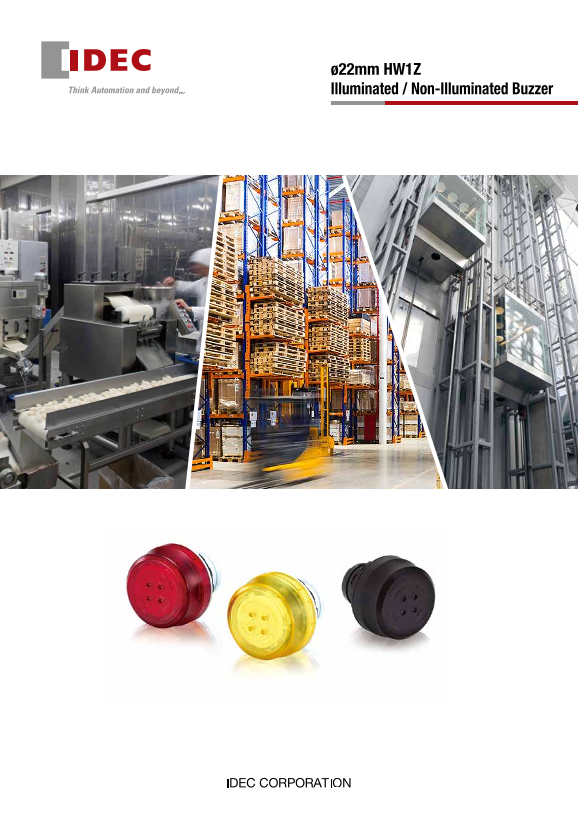
Page 1 Text Content
ø22mm HW1Z Illuminated / Non-Illuminated Buzzer
ø22mm HW1Z Illuminated / Non-Illuminated Buzzer
Safety Precautions ø22mm HW1Z • Turn off the power to the HW1Z before installation, removal, wiring, • Prevent metal fragments and pieces of wire from dropping inside Illuminated / Non-Illuminated Buzzer
Part No. maintenance, and inspection. Failure to turn power off may cause when installing or wiring the HW1Z. Otherwise fire, failure, or
Shape Illumination Color Sound Package Quantity
(Ordering No.)
electrical shocks or fire hazard. malfunction may be caused.
Illuminated Buzzer
• For wiring, use wires of a proper gauge to meet the voltage and
HW1Z-P1F2PQ4R Red current requirements.
Intermittent
HW1Z-P1F2PQ4Y Yellow
Operating Instructions
Panel Mounting Wire removal
Non-Illuminated Buzzer
Push in the white wire removal part above the wire ports using a small
HW1Z-2PQ4B Steady • Insert the HW1Z into the panel cut-out from the front, and tighten the
flat screw driver, and pull out the wire.
locking ring from the back.
Note for panel mounting Panel
Small flat screwdriver
HW1Z-F2PQ4B Intermittent • Use the optional locking ring wrench (MW9Z-T1)
Use an optional screwdriver (BC1S-SD0) or a commercial screwdriver
to tighten the locking ring to a recommended Locking
(flat, 2.5mm-wide blade)
tightening torque of 1.5 to 2.0 N·m. Ring
• Do not use pliers and do not tighten excessively,
Note for wiring
otherwise the HW1Z may be damaged.
• Make sure that the terminal is not constantly pulled by the wire.
• See website for details on approvals and standards.
• Wiring must be performed in environments of –5 to +50°C.
Wiring
• Do not damage the conductor wire when stripping the wire insulation. Solid wire • Do not use wires with bent or deformed conductors wires. Deformed wiring Specifications may cause faliures such as strength degradation and overheating.
Strip the wire insulation 8 mm from the end and insert into the terminal.
• Connect one wire per terminal. Connecting two wires to a terminal may cause
Make sure that the wire does not loosen.
Specifications and Ratings Dimensions All dimensinos in mm. loose wiring and strength degradation.
Stranded wire with ferrule • Do not solder the conductor lines. Connecting soldered stranded wires may
Rated Insulation Voltage 30V Buzzer only
Clamp a ferrule with a conductor wire length of 8mm and insert into loose wiring and strength degradation.
Rated Voltage 12 to 24V DC Rubber Gasket
Panel Thickness 0.8 to 6 mm the terminal. Make sure that the wire does not loosen. • If a stranded wire has loose wires, twist the conductor wires before
Locking Ring
Voltage Range 10.8 to 26.4V DC connection. However be careful not to twist too much.
3.3 ø3 Recommended Ferrules
Illuminated: 18m A (24V DC), 8m A (12V DC)
Rated Current Non-Illuminated Phoenix Contact
Operating Conditions
(effective value) (Steady sound): 9m A (24V DC), 4m A (12V DC)
Without sleeve With sleeve
(Intermittent sound): 7m A (24V DC), 3m A (12V DC) Do not use the HW1Z in the following locations.
For 0.5mm2: A0,5-8 For 0.25mm2: AI0,25-8YE
Inrush Current 100m A maximum • Exposure to direct sunlight
0.5 For 0.75mm2: A0,75-8 For 0.5mm2: AI0,5-8WH 17.619.7
90d B min. at 0.1m (24VDC)
For 1.0mm2: A1-8 For 0.75mm2: AI0,75-8GY • Subject to corrosive or flammable gases
Sound Volume
70d B min. at 1m (24V DC, equivalent value)
(of HW1Z itself)
With terminal rubber boot
84d B min. at 0.1m (12V DC)
(at 25ºC)
Stranded wire
64d B min. at 1m (12VDC, equivalent value) Cut here when cable size is ø5.5 to 6.5 (*1)
Cut here when cable size is ø6.5 to 7.5 (*1) Strip the wire insulation 8mm from the end and push Wire Removal Part
Sound Frequency
Buzzer 2,200 to 2,450Hz Cut here when cable size is ø7.5 to 8.5 (*1) (white)
in the wire removal part above the wire port using a
(at 25ºC)
small flat screwdriver. Release the wire removal part.
Illuminated: Intermittent
Sound Type Make sure that the wire does not loosen.
Non-Illuminated: Steady/Intermittent
Intermittent Cycle
105 cycles/minute approx. (1.75Hz approx.)
(at 25ºC)
Bellows (*2)
Illumination Type Flashing 17 to 22
Illumination
Flash Cycle (at 25ºC) 105 cycles/minute approx. (1.75Hz approx.) 54 to 59 58 to 63
Operating Temperature –20 to +50ºC (no freezing) 62 to 67
66 to 71
Operating Humidity 20% to 85% RH (no condensation)
Storage Temperature –30 to +80ºC (no freezing) *1: ø4.5-5.5 cable needs no cutting. *2: The bellows must be 17 to 22mm long after installing the terminal rubber boot.
Insulation Resistance 100MΩ minimum (at 500V DC megger)
*3: Maintain a cable angle of 45° max. to the HW1Z axis.
Between live and earthed metal parts:
Dielectric Strength
1000V AC, 1 minute Operation extremes: 5 to 55Hz, amplitude 0.5mm
Vibration Resistance
Damage limits: 5 to 55Hz, amplitude 0.5mm Terminal Arrangement Mounting Hole Layout Operation extremes: 100 m/s2 (botom view) www.idec.com
Shock Resistance +0.2 Head Office
Damage limits: 1,000 m/s2 3.2 R0.8 max.
6-64, Nishi-Miyahara-2-Chome, Yodogawa-ku, Osaka 532-0004, Japan
Panel front: IP65 (IEC 60529)
USA IDEC Corporation Tel: +1-408-747-0550 [email protected] Hong Kong IDEC Izumi (H.K.) Co., Ltd. Tel: +852-2803-8989 [email protected]
Terminal: IP40 (IEC 60529)
Degree of Protection Germany APEM Gmb H Tel: +49-40-25 30 54 - 0 [email protected] China/Shanghai IDEC (Shanghai) Corporation Tel: +86-21-6135-1515 [email protected]
IP54 (with terminal rubber boot) (IEC
Singapore IDEC Izumi Asia Pte. Ltd. Tel: +65-6746-1155 [email protected] China/Shenzhen IDEC (Shenzhen) Corporation Tel: +86-755-8356-2977 [email protected]
+0.4 Thailand IDEC Asia (Thailand) Co., Ltd Tel: +66-2-392-9765 [email protected] China/Beijing IDEC (Beijing) Corporation Tel: +86-10-6581-6131 [email protected]
Terminal Style Push-in Terminals X1 and X2
2.3 Australia IDEC Australia Pty. Ltd. Tel: +61-3-8523-5900 [email protected] Japan IDEC Corporation Tel: +81-6-6398-2527 [email protected]
have no polarity. ø2
Panel cut-out
Solid wire/ferrule (without sleeve): 0.2 to 1.5 mm2 Taiwan IDEC Taiwan Corporation Tel: +886-2-2698-3929 [email protected]
Applicable Wire
Ferrule (with sleeve): 0.2 to 0.75 mm2 +0.2 3.2 hole is for anti-rotation. Not required when nameplate/anti-rotation Speci cations and other descriptions in this brochure are subject to change without notice.
Weight (approx.) 17g
is not used.
2018 IDEC Corporation, All Rights Reserved.
EP1690-0 OCTOBER 2018
ax. (*3) 45° m
Page Summary Contents For IDEC HW1Z Illuminated Buzzer Sample and Brochure
Manual Details
| Brand | IDEC |
|---|---|
| Pages | 5 |
| File Size | 1.66 MB |
| Published | June 05, 2026 |
Enter the captcha to get the download link:

Frequently Asked Questions
What safety precautions must be followed before servicing the buzzer?
Always turn off the power to the HW1Z before installation, removal, wiring, maintenance, and inspection.
How do I properly wire the illuminated buzzer?
Use wires of a proper gauge for current requirements. Strip 8mm from the insulation, connect one wire per terminal, and ensure the wire does not loosen or get pulled.
What is the recommended tightening torque for the locking ring?
The recommended tightening torque is 1.5 to 2.0 N·m. Do not use pliers or over-tighten.